
Electric arc pulse welder with short circuit control

一种电弧焊机、脉冲波形的技术,应用在电弧焊接领域

Inactive Publication Date: 2005-10-05
LINCOLN GLOBAL INC
View PDF0 Cites 9 Cited by
  • Summary
  • Abstract
  • Description
  • Claims
  • Application Information

AI Technical Summary

Problems solved by technology

The invention is used with gas shielding and preferably with solid metal welding wire

Method used


Image

  • Electric arc pulse welder with short circuit control
  • Electric arc pulse welder with short circuit control
  • Electric arc pulse welder with short circuit control

Examples


Embodiment Construction

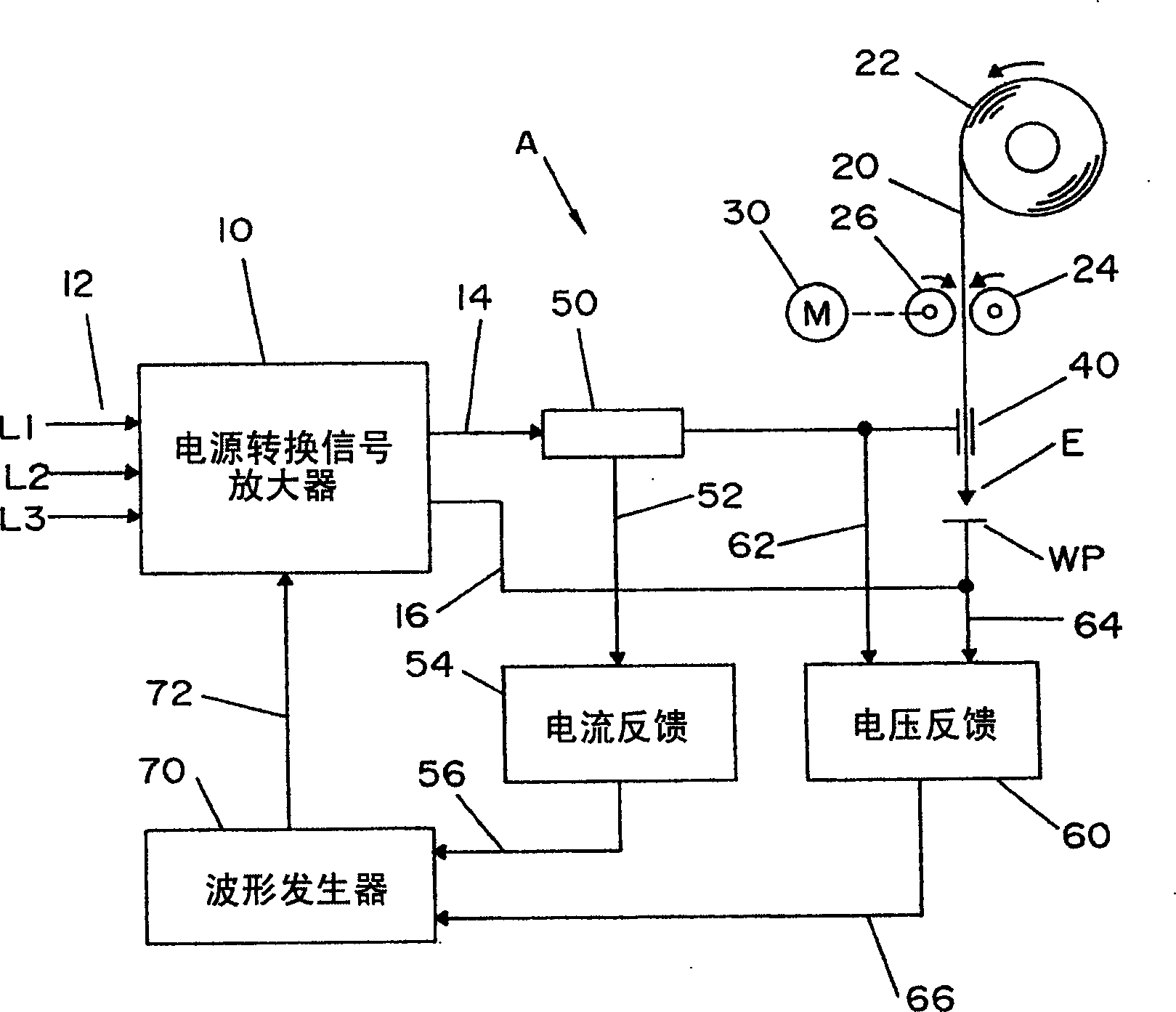
[0022]The pulsed spray welding process improved by the use of the present invention employs a standard arc welder, such as welder A shown in Figure 1, where power source 10 is a high slew rate power source, such as an inverter or circuit breaker The device has an input power supply 12, shown as a three-phase electrical input. Of course, a single phase input power source with a different voltage and frequency or even a motor or engine driven generator or alternator could be used to direct the electrical energy to the converter or power source 10 . The output leads 14, 16 are connected in series via the electrode E and the workpiece WP to perform the welding process by directing current flow between the electrode and the workpiece. In accordance with standard practice, the electrode is a continuous wire, which in the prior art is a flux-cored wire, but in the present invention is a solid-cored wire that can be used. This was not possible in some off-shore applications prior to ...


PUM


Abstract

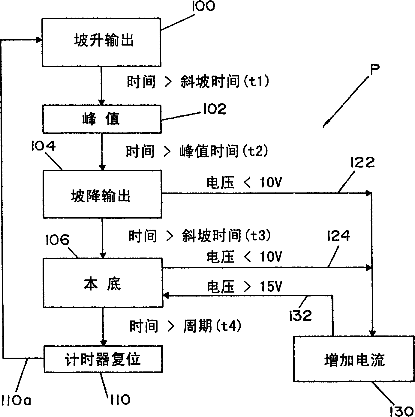
An electric arc welder with a waveform generator controlled to create a welding process involving current flow between an electrode and a workpiece wherein the welding process comprises a succession of pulse waveforms, each having a current ramp up portion, a peak current portion, a current ramp down portion and a background current portion, a voltage sensing circuit to sense a short circuit between the electrode and the workpiece and a reset circuit to reset the waveform generator upon sensing of a short circuit. The preferred electrode is a solid wire which may be in the form of a metal cored wire.

Description

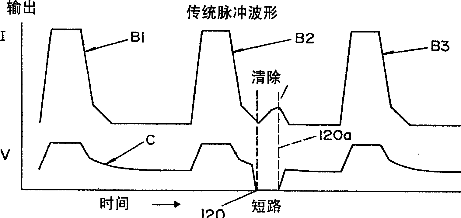
technical field [0001] The invention relates to arc welding technology, in particular to an arc pulse welding machine with short-circuit control. Background technique [0002] When using the waveform technique for pulse spray welding, a series of waveforms are created, wherein each waveform includes a current ramp portion, a peak current portion, a current ramp portion and a background current portion. A single waveform is typically created by a series of short-circuit current pulses controlled by a pulse width modulator that provides pulses of a given duration to operate a high-speed switching power supply, such as an inverter or an equivalent interrupter . The profile of a single waveform created in a continuous fashion to provide a pulsed spray welding process is controlled by a waveform generator or waveform shaper having an output control signal. This digital or analog signal determines the duty cycle of the pulses of the pulse wave modulator operating at frequencies ...

Claims


Application Information

Patent Timeline
Patent Type & Authority Applications(China)
IPC IPC(8): B23K9/073B23K9/09B23K9/10H02M9/00
CPCB23K9/092B23K9/0732B23K9/095B23K9/093
Inventor 杰弗里·T.纳贾姆史蒂文·R.彼得斯
Owner LINCOLN GLOBAL INC
Learn More