
Main burner equipment with outer rotational flow and inner direct flow

A main burner and external swirl technology, applied in burners, burners burning powder fuel, combustion types, etc., can solve the problem of unfavorable pulverized coal flow ignition and stable combustion, reduce jet entrainment of high temperature flue gas, Weakening of the nozzle jet rigidity and other problems, to ensure the stability and economy, to ensure the fullness of the furnace flame, and to improve the ignition conditions.

Active Publication Date: 2005-10-26
HUAZHONG UNIV OF SCI & TECH
View PDF0 Cites 2 Cited by
  • Summary
  • Abstract
  • Description
  • Claims
  • Application Information

AI Technical Summary

Problems solved by technology

For DC burners, in order to strengthen the ignition, a bluff body is usually installed at the nozzle of the DC main burner to enhance the entrainment of high-temperature flue gas by the return flow, but this will weaken the rigidity of the jet flow at the nozzle and reduce the penetration of the pulverized coal flow in the furnace. For swirl burners, in order to increase the penetration depth of pulverized coal gas flow in the furnace, increasing the flame fullness usually reduces the swirl intensity, but this will reduce the impact of the jet on the high-temperature flue gas. Entrainment, which is not conducive to the ignition and stable combustion of pulverized coal airflow

Method used


Image

  • Main burner equipment with outer rotational flow and inner direct flow
  • Main burner equipment with outer rotational flow and inner direct flow
  • Main burner equipment with outer rotational flow and inner direct flow

Examples


Embodiment Construction

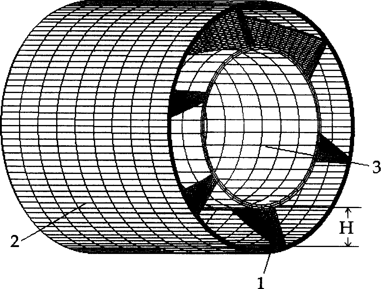
[0026] figure 1 It is the structure of the guide vane of the burner on the duct of the present invention, which is composed of the main primary air pulverized coal flow pipe 2, the duct 3 and the guide vane 1, and the height H of the vane in the duct.

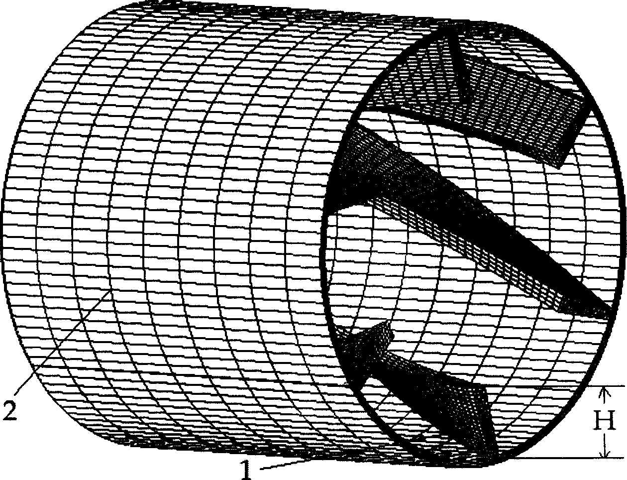
[0027] figure 2 The guide vane of the burner of the present invention has no duct structure, and is composed of the primary air pulverized coal flow pipe 2 and the guide vane 1, and the height H of the vane in the duct.

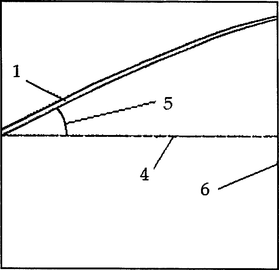
[0028] image 3 It is a schematic diagram of the angle between the guide vane and the axis of the main primary air pulverized coal flow pipe; where the guide vane 1, the axis of the main primary air pulverized coal flow pipe 5, the angle between the guide vane and the axis of the main primary air pulverized coal flow pipe 6 , exit 7.

[0029] Figure 4 It is a perspective view of the structure of the present invention with a conduit when the distance S from the guide vane to the outlet of the main primary...


PUM

PropertyMeasurementUnit
Angleaaaaaaaaaa

Abstract

The invention is the outer cyclone inner direct flow main combustor device and belongs to the combustor device of boiler. The purpose of the invention is to produce the backflow area and the stable combustion. One device of the invention is to evenly arrange the delivery blades between the primary air diverting tube and the delivery tube, and the inside diameter of the delivery tube is as 0.5-0.7 times as the diameter of the primary air diverting tube. The other device is to evenly arrange the delivery blades in the inner chamber of the primary air diverting tube, and the axial height of the delivery blades is as 0.1-0.5 time as the semi-diameter of the primary air diverting tube. The invention through changing the opposite angles, the number, the length and the height of the delivery blades and the lengths and the section of the delivery tube to change the intensity and the size of the cyclone amount to adapt the characteristics of different fuels and ensure the stability and economy of the boiler combustion. The invention has simple structure and convenient equipment.

Description

technical field [0001] The invention belongs to the field of burners for boiler equipment and is suitable for pulverized coal combustion furnaces. Background technique [0002] As combustion equipment, boilers are widely used in various industries. The burner is the main equipment for boiler equipment to achieve good combustion effect, and plays a very important role in the safe operation and economic benefits of the boiler. It organizes the aerodynamic field in the furnace reasonably through pulverized coal concentration technology, graded combustion technology, etc., and obtains a reasonable The concentration distribution of pulverized coal in the ignition area, the residence time of particles and the ignition distance are used to obtain good ignition characteristics, low-load stable combustion characteristics and operating economy. In the past few decades, scientists and engineers have successfully developed different burners. Pulverized coal burners can be roughly divid...

Claims


Application Information

Patent Timeline
IPC IPC(8): F23D1/00
Inventor 张志国周怀春方庆艳
Owner HUAZHONG UNIV OF SCI & TECH
Learn More