Top-spraying self-priming regeneration tower

A self-priming, regeneration tower technology, applied in the separation of dispersed particles, chemical instruments and methods, separation methods, etc., can solve the problem of insufficient separation time of solution and sulfur bubbles, insufficient separation time of sulfur bubbles and solution, and desulfurization absorption reaction. Insufficient time and other problems, to achieve the effect of stable and easy-to-control desulfurization operation, eliminating the need for special air compressors, good economic benefits and social effects

Inactive Publication Date: 2014-03-26
JIANGSU ZHONGXIAN GRP CO LTD
View PDF6 Cites 0 Cited by
  • Summary
  • Abstract
  • Description
  • Claims
  • Application Information

AI Technical Summary

Problems solved by technology

The technical key is that the separation time between the solution and the sulfur bubbles is not sufficient, and the desulfurization absorption reaction time is not sufficient, so the solution has a lot of suspended sulfur, the circulating solution is not clear, and the nozzle and packing are easy to block
[0006] The above three kinds of desulfurization liquid regeneration equipment have the common disadvantages of insufficient separation time between sulfur bubbles and the solution, unclear solution interface, and short reaction time.
The disadvantage of the regenerative tower is that after the air and solution are pressed into the bottom premixer, the gas-liquid two-phase from the bottom of the tower to the top of the tower cannot maintain good dispersion due to the pressure of the liquid column, and it is easier to form a continuous phase, so the actual oxidation reaction small area
After the sulfur bubbles and solution enter the top amplification part of the tower, whether it is a tank or a tower device, the separation time is insufficient.

Method used


Image

  • Top-spraying self-priming regeneration tower

Examples


Embodiment Construction

[0021] The present invention will be further described below in conjunction with specific embodiments.

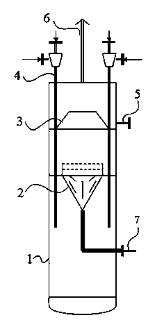
[0022] Such as figure 1 As shown, the tower body 1 of the top-spray self-priming regeneration tower is cylindrical in shape, and a foam separator 2 is arranged in the tower body 1; a foam collection weir is arranged in the tower body 1 between the foam separator 2 and the top of the tower 3. A sulfur bubble outlet pipe 5 is provided on the tower body 1 between the foam separator 2 and the top of the tower; a self-priming jet regenerator 4 is arranged on the tower, and the solution outlet at the lower end of the self-priming jet regenerator 4 is in the foam Between the separator 2 and the bottom of the tower, the solution outlet of the self-priming jet regenerator is connected to the solution outlet pipe 7, and the solution outlet pipe 7 is a "Π" shaped pipe. A regeneration waste gas discharge pipe 6 is arranged on the top of the tower, and nozzles for cleaning the waste ga...


PUM


Abstract

The invention discloses a top-spraying self-priming regeneration tower which comprises a tower body and a self-priming spraying regenerator. A foam separator and a foam colleting weir are arranged in the tower body; the foam colleting weir is arranged between the foam separator and the top of the tower; the self-priming spraying regenerator is inserted into the tower body so as to ensure that a solution outlet of the self-priming spraying regenerator is positioned between the foam separator and the bottom of the tower; a sulfur bubble lead-out pipe is arranged on the tower body between the foam colleting weir and the top of the tower; a regenerative exhaust gas discharge pipe is arranged at the top of the tower; and the solution outlet of the self-priming spraying regenerator is connected with a solution lead-out tube. The top-spraying self-priming regeneration tower has the advantages that the material consumption is less, the steel consumption of the tower is 20-30 % less than that of a tower type desulfurizer, compared with a high tower regenerating unit, the operating power consumption of the tower is low, the pressure of a circulating pump is reduced by half, an air compressor is saved, the operating power cost is low, the desulphurization operation is stable and easy to regulate and control, the desulphurization efficiency is high, and the salt is slowly produced in the secondary reaction.

Description

technical field [0001] The invention relates to a gas desulfurization process device, in particular to a top-spray self-priming regeneration tower. Background technique [0002] The wet catalytic oxidation desulfurization and decyanation process of gas must include a hydrogen sulfide absorption tower and a desulfurization circulating liquid oxidation regeneration tower. At present, there are three types of desulfurization and decyanation process devices in the domestic coal chemical industry. [0003] The first type is a traditional two-tower device, which is a desulfurization absorption tower and a high solution regeneration tower. The regeneration tower is 15-18m higher than the desulfurization tower. The top of the regeneration tower is equipped with a solution amplification part and a sulfur bubble separation amplification part. The solution separated from the top of the tower passes through the liquid level regulator, and uses the high pressure difference to flow to th...

Claims


Application Information

Patent Timeline
Patent Type & Authority Patents(China)
IPC IPC(8): B01D53/78B01D53/48
Inventor 袁长胜张超群崔平刘家林张巨水
Owner JIANGSU ZHONGXIAN GRP CO LTD
Why Eureka
Try Eureka