
Portable gas detector

A gas detector and portable technology, applied in the field of portable gas detectors, can solve the problems of high price, high measurement lower limit, large size of the instrument, etc., and achieve the effects of good gas flow condition, improved information content, and improved stability

Inactive Publication Date: 2005-10-26
ZHEJIANG UNIV
View PDF1 Cites 33 Cited by
  • Summary
  • Abstract
  • Description
  • Claims
  • Application Information

AI Technical Summary

Problems solved by technology

At present, commercialized electronic noses have appeared in some European and American countries, but these instruments are large in size and expensive, and cannot meet the requirements of on-site detection and portability.
Chinese patent CN02111963.5 provides a portable intelligent electronic nose and its preparation method. Since there is no enrichment device, the measurement lower limit is high, and the detection gas is single, and the mixed gas cannot be detected at the same time.

Method used


Image

  • Portable gas detector
  • Portable gas detector
  • Portable gas detector

Examples


Embodiment 1

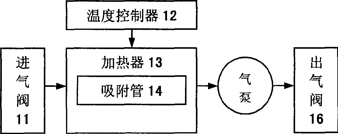
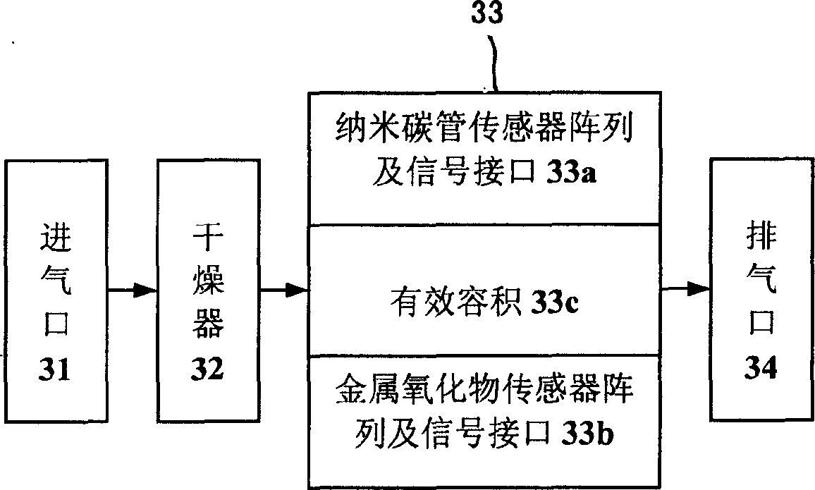
[0020] A portable gas detector, equipped with a gas enrichment device 1, a buffer air bag 2 and a measuring gas chamber 3, the gas to be measured passes through the enrichment device 1, the buffer air bag 2 and then enters the measuring gas chamber 3, and the gas to be measured passes through the enrichment After the device 1, its concentration is increased to 10 times of the original; the gas sensor array and its signal interface are arranged in the sealed cavity 33 of the measurement gas chamber 3, and the gas sensor array is composed of 4 parallel metal oxide sensors and 4 parallel Composed of carbon nanotube sensors; the enrichment device 1 is composed of an intake valve 11, a temperature controller 12 controlled by a control circuit, a heater 13, an adsorption tube 14 equipped with an adsorbent, an air pump 15, and an air outlet valve 16; the measuring air chamber 3. It is composed of an air inlet 31, a dryer 32, a cubic sealed cavity 33, and an exhaust port 34. The carbon...

Embodiment 2

[0025] A portable gas detector, the gas to be measured passes through the enrichment device 1 and the buffer air bag 2 in turn, and then enters the measurement gas chamber 3, and the concentration of the gas to be measured increases to 100 times after passing through the enrichment device 1; the metal oxide sensor adopts Commercially available SnO 2 The working temperature of the sensor is controlled at 300-420 ° C. The carbon nanotube sensor is provided by the National Professional Laboratory of Biosensors, Zhejiang University; TENAX-G is used as the adsorbent, and the sampling temperature is controlled at 0.2 L / min for 15 minutes. Thermal desorption at 25°C and 200°C to achieve gas enrichment; single-chip microcomputer MSP430F449 realizes sensor signal acquisition, preprocessing, pattern recognition after conditioning, and controls display, keyboard input, printer output, gas collection, thermal desorption and other processes , The effective volume of the measuring air chamb...


PUM


Abstract

It is a kind of portable gas detecting device. It has the gas-collecting device(1), the buffer air-pocket(2) and the gas measuring room(3). The gas to be measured will by steps go through(1), (2) and then it will go into (3). After the gas goes through (1), the concentration of the gas will improve to 10-100 times of the former concentration. The gas sensor group and the signal interface are set in the seal cavity (33) of (3), and the gas sensor group is made up of 4 parallel metal oxide sensors and 4 parallel carbon nanometer pipe sensors. Compared with existing technology, this invention has the merits below. Firstly the detecting low limit of the machine is 1-2 orders lower than that of the sensor itself. Secondly the protected gas measuring room can decrease the effect on the sensor from the temperature, humidness and gas streaming. The dynamic detecting technology can fully use the sensitive area of the sensor, and increase the information content of the response signal. At last, the device can be used for field detecting.

Description

technical field [0001] The invention relates to a novel portable gas detector. Background technique [0002] Gas detection technology plays an increasingly important role in the fields of industry and agriculture, environmental monitoring, and daily life. At present, the environmental protection department mainly uses gas chromatography as a gas detection instrument, and sometimes uses accurate biological and chemical analysis for effective detection. , although the detection accuracy and sensitivity are very high, the instrument is expensive, the cost is high, and the detection takes a long time, so it cannot be detected on-site, which has great limitations. Since the 1980s, artificial olfactory-electronic nose technology has developed rapidly. The electronic nose is mainly composed of a gas sensor array and a pattern recognition system, which can identify one or more gases qualitatively or even quantitatively. At present, commercial electronic noses have appeared in some ...

Claims


Application Information

Patent Timeline
IPC IPC(8): G01N27/00
Inventor 陈裕泉潘敏方向生朱丹华
Owner ZHEJIANG UNIV
Learn More