

Combined detector and combined detecting method for switch state of DC ground resistance
A combined detection and DC grounding technology, applied in the direction of fault location, etc., can solve the problems of difficult batch production, undetectable, cumbersome production process, etc., to reduce production cost and maintenance cost, facilitate production and maintenance, and have good instrument consistency Effect
- Summary
- Abstract
- Description
- Claims
- Application Information
AI Technical Summary
Problems solved by technology
Method used
Image

Examples
Embodiment 1
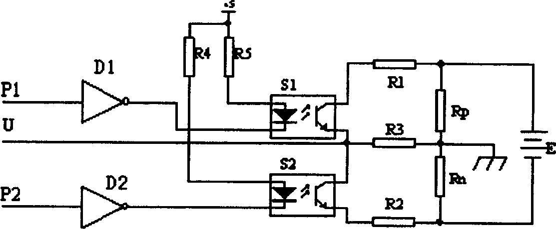
[0036] Embodiment 1: attached figure 2 As one of the embodiments, the first controllable electronic switch S1 and the second controllable electronic switch S2 adopt two photoelectrically isolated semiconductor switches (also known as photoelectric relays), and the control signals P1 and P2 are from CPU or other control circuits. Control signal; the voltage of the voltage sampling point U passes through the absolute value circuit and the sign judgment circuit, and is input into the analog input port and the digital input port of the microcomputer; the control signal P1 is high level, and the control signal P2 is low level, then the first The first controllable electronic switch S1 is turned on, and the second controllable electronic switch S2 is turned off; when the control signal P2 is at a high level and the control signal P1 is at a low level, the second controllable electronic switch S2 is turned on, and the first controllable electronic switch S2 is at a low level. The el...
Embodiment 2
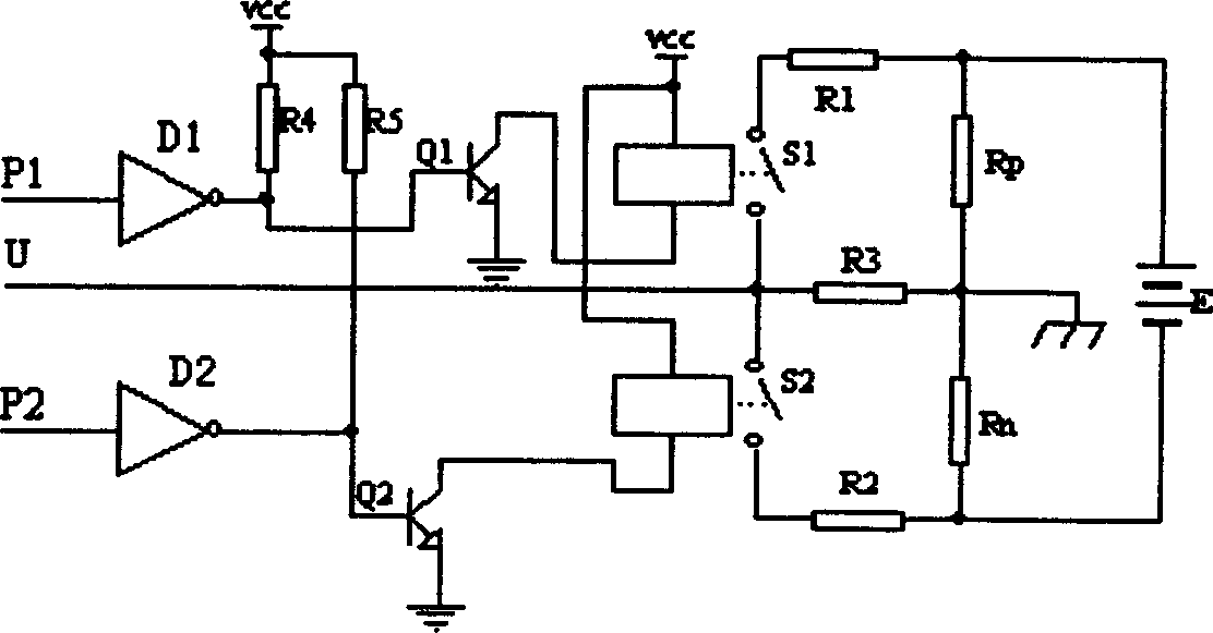
[0039] Embodiment 2: attached image 3 It is the second embodiment of the present invention, the difference is that the first controllable electronic switch S1 and the second controllable electronic switch S2 are realized by relays. The control signals P1 and P2 are control signals from the CPU or other control circuits; the voltage of the voltage sampling point U passes through the absolute value circuit and the symbol judgment circuit, and then input to the analog input port and the digital input port of the microcomputer; the control signal P1 is low level, the control signal P2 is high level, the first controllable electronic switch S1 is turned on, and the second controllable electronic switch S2 is turned off; the control signal P1 is high level, and the control signal P2 is low level, then the second The second controllable electronic switch S2 is turned on, and the first controllable electronic switch S1 is turned off; when the control signals P1 and P2 are both at low...
PUM
 Abstract
Description
Claims
Application Information