Flue gas treatments to reduce NOx and CO emissions

A flue gas and flue technology, applied in chemical instruments and methods, chemical/physical processes, physical/chemical process catalysts, etc., can solve the problems of high cost and operating cost

Inactive Publication Date: 2005-10-26
英特凯特公司
View PDF3 Cites 22 Cited by
  • Summary
  • Abstract
  • Description
  • Claims
  • Application Information

AI Technical Summary

Problems solved by technology

[0006] Reduce NO x The flue gas treatment method is

Method used


Image

  • Flue gas treatments to reduce NOx and CO emissions
  • Flue gas treatments to reduce NOx and CO emissions

Examples


Embodiment

[0041] The following examples are only to illustrate the present invention, and are not intended to limit the scope of protection of the appended claims.

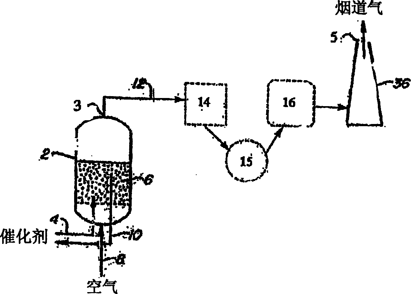
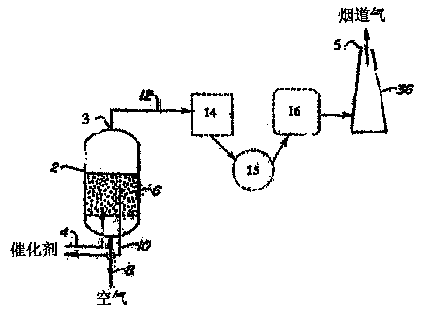
[0042] An FCC unit with typical operating conditions was used in this test. For example, an FCC unit with a regenerator temperature of about 1350°F, a feed rate of about 90,000 bbl / day, a conversion of about 75%, and excess O at the regenerator exit / stack start 2 The concentration is about 0.5%; excess O in the flue (at the tail end of the flue) 2 The concentration was about 1%; the basic nitrogen content in the feed was about 300 ppm.

[0043] refer to figure 1 , before adding the composition of the invention to the FCC unit, measure NO in the regeneration furnace 2 of the FCC unit as close as practically possible to the beginning of the flue 3 and the tail end of the flue 5 x and CO emissions.

[0044] The composition of the present invention was added to the FCC regenerator in an amount of about 0.04% by weight of th...


PUM


Abstract

The invention provides compositions and methods to reduce NOx emissions from the flue gas of a fluid catalytic cracking (FCC) unit (10). The invention also provides methods for reducing CO emissions from the regenerator (2) and/or the flue of an FCC unit. The compositions (4) of the invention comprise copper and/or cobalt and a carrier. The carrier can be, for example, hydrotalcite like compounds, spinels, alumina, zinc titanate, zinc aluminate, zinc titanate/zinc aluminate, and the like.

Description

[0001] related application [0002] This application claims priority to US Provisional Application No. 60 / 402,710, filed August 13,2002. field of invention [0003] The present invention provides for the reduction of NO in the flue gas of a fluid catalytic cracking (FCC) unit x Compositions and methods for CO emissions. Background technique [0004] figure 1 Schematic showing the regeneration furnace and flue of the FCC unit. The coked catalyst is transported from the cracking tube (not shown) of the FCC unit to the catalyst regeneration furnace 2 through the transport pipe 4 . The spent catalyst is regenerated in the fluidized bed 6 by burning the coked catalyst in the presence of air which is introduced into the regenerator 2 through an air duct 8 . The regenerated catalyst returns to the cracking tube through the transfer pipeline 10 . NO formed in regeneration furnace 2 x (eg, NO, NO 2 , N 2 O, N 2 o 4 , N 2 o 5 ) and CO flow out of the fluidized bed 6, and f...

Claims


Application Information

Patent Timeline
IPC IPC(8): B01D53/94B01D53/86B01J23/72B01J38/36C01B21/00
CPCB01D53/865B01J38/36B01D53/56C01B21/00
Inventor 艾伯特·A·菲尔海利希
Owner 英特凯特公司
Why Eureka
Try Eureka