Production method of high strength polycrystalline ceramic spheres

a production method and polycrystalline ceramic technology, applied in the direction of synthetic resin layered products, natural mineral layered products, wellbore/well accessories, etc., can solve the problems of small changes in porosity or pore size, pore size, and inability to provide uniform coating of individual particles, etc., to achieve excellent mechanical strength and tolerance to solvents

Inactive Publication Date: 2007-05-22
RICE UNIV
View PDF7 Cites 43 Cited by
  • Summary
  • Abstract
  • Description
  • Claims
  • Application Information

AI Technical Summary

Benefits of technology

[0012]Embodiments of the present invention comprise polycrystalline alumina and aluminate hollow spheres with a hardness approaching crystalline sapphire as well as applications utilizing such spheres. One such application is the use of hollow spheres in filtration membranes. The application of ceramic membranes in pollution prevention, resource recovery and waste treatment activities is increasing due to their excellent mechanical strength and tolerance to solvents, as well as to extremes of pH, oxidation, and temperature. In addition, the amphoteric properties of ceramic surfaces result in uniquely versatile membranes for water and waste-water treatment.

Problems solved by technology

Conventional methods to produce hollow ceramic spheres are vapor deposition, sputtering, molecular beam deposition and electrolytic deposition; however, these processes do not always provide a uniform coating of individual particles.
The preparation techniques used by various researchers vary the drying or sintering conditions, which result in small changes in porosity or pore size.
However, for membranes produced by sol-gel techniques the pore size is generally limited to the size distribution of the precursor particles before sintering, which is difficult to control.
Unfortunately, in order to ensure a defect free membrane, a thickness of 1-2 μm is required.
However, this also required multiple process steps and each layer may result in a decrease in flux.

Method used


Image

  • Production method of high strength polycrystalline ceramic spheres
  • Production method of high strength polycrystalline ceramic spheres
  • Production method of high strength polycrystalline ceramic spheres

Examples


examples

Hollow Spheres

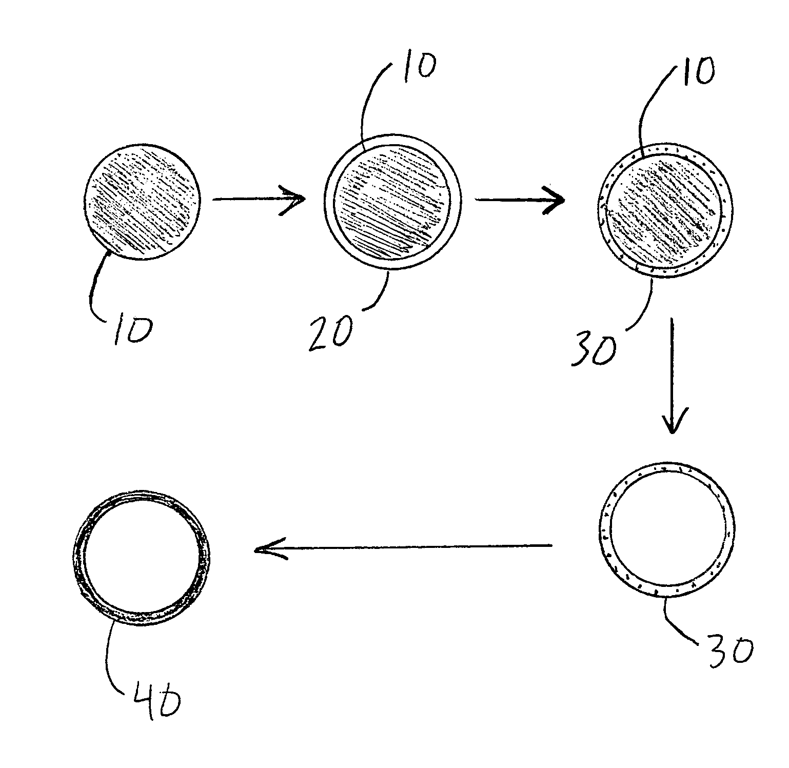
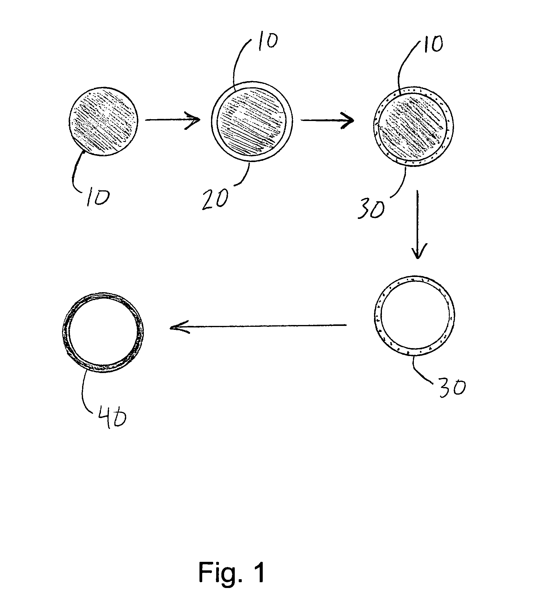
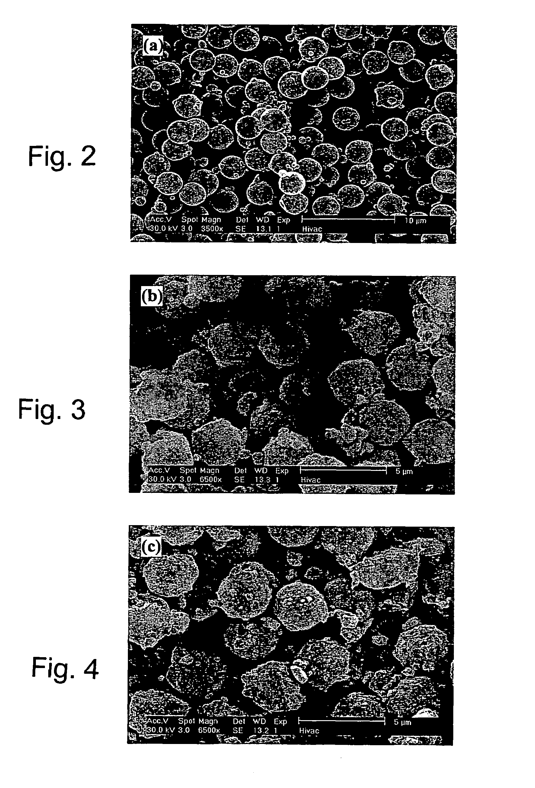
[0038]An acetate-alumoxane (A-alumoxane) (not shown) was prepared according to the method described in Chem. Mater. 9 (1997) 2418 by R. L. Callender, C. J. Harlan, N. M. Shapiro, C. D. Jones, D. L. Callahan, M. R. Wiesner, R. Cook, and A. R. Barron, which is incorporated herein by reference. Aqueous solutions of alumoxane were then degassed before use. Dry-form polystyrene beads 10, such as those available from Polysciences, Inc. and shown in FIG. 2, were preferably used. Beads of polymers other than polystyrene may be used, so long as the polymer is soluble in a solvent. Likewise, beads of other materials may be used, so long as they are soluble in a solvent that will not damage the alumoxane coating.

[0039]Beads 10 were then coated with the aqueous solution of A-alumoxane, as shown in the SEM image in FIG. 3. The aqueous solution of A-alumoxane may range from 1-10 weight percent. The aqueous solution of A-alumoxane more preferably ranges from 2-8 weight percent, and m...


PUM

PropertyMeasurementUnit
diameteraaaaaaaaaa
temperatureaaaaaaaaaa

Abstract

A method for making hollow spheres of alumina or aluminate comprises: coating polymeric beads with an aqueous solution of an alumoxane, drying the beads so as to form an alumoxane coating on the beads; heating the beads to a first temperature that is sufficient to convert the alumoxane coating to an amorphous alumina or aluminate coating and is not sufficient to decompose the polymeric beads; dissolving the polymeric bead in a solvent; removing the dissolved polymer from the amorphous alumina or aluminate coating; and heating the amorphous alumina or aluminate coating to a second temperature that is sufficient to form a hollow ceramic sphere of desired porosity and strength. The hollow spheres can be used as proppants or can be incorporated in porous membranes.

Description

CROSS-REFERENCE TO RELATED APPLICATIONS[0001]The present application claims the benefit of U.S. Provisional Application Ser. No. 60 / 445,551, entitled High Strength Polycrystalline Ceramic Spheres, and U.S. Provisional Application Ser. No. 60 / 445,586, entitled Method of Making Hierarchical Ceramic Ultrafiltration Membranes, both filed Feb. 6, 2003.SPONSORED RESEARCH OR DEVELOPMENT[0002]Research leading to the present invention was supported in part by the federal government under Grant No. DMI-9613068 awarded by the National Science Foundation. The United States government may have certain rights in the invention.BACKGROUND OF THE INVENTION[0003]Recognition that the macroscopic properties of materials depend not only on their chemical composition, but also on the size, shape and structure, has spawned investigations into the control of these parameters for various materials. In this regard, the fabrication of uniform hollow spheres has recently gained much interest. Hollow capsules w...

Claims


Application Information

Patent Timeline
Patent Type & Authority Patents(United States)
IPC IPC(8): B05D3/02B01D71/02B01JB01J13/02B32B5/16C04B28/24C04B35/628C04B38/00C09K8/80
CPCB01D67/0088B01J13/02C04B28/24C04B35/628C04B35/62813C04B35/62821C04B38/009C09K8/80C09K8/805B01D71/025C04B35/10C04B38/0022C04B38/04C04B40/0263C04B40/0268C04B14/301Y10T428/2982B01D2323/08C04B2111/00801C04B2235/3217C04B2235/78C04B2235/96
Inventor BARRON, ANDREW R.DEFRIEND, KIMBERLY A.
Owner RICE UNIV
Why Eureka
Try Eureka