Super-voltage transmission line monitoring and detecting robot mechanism

A technology for patrolling robots and power lines, applied to manipulators, manufacturing tools, etc., can solve the problems of limited obstacle-surmounting ability, difficult control, complex structure, etc., and achieve strong obstacle-surmounting ability, reduce the weight of the mechanism, and have a wide range of applications Effect

Inactive Publication Date: 2005-11-02
SHENYANG INST OF AUTOMATION - CHINESE ACAD OF SCI
View PDF0 Cites 50 Cited by
  • Summary
  • Abstract
  • Description
  • Claims
  • Application Information

AI Technical Summary

Problems solved by technology

[0003] In order to overcome the disadvantages of the above-mentioned moving mechanism, such as complex structure, heavy weight, high energy consumption, limited obstacle-surmounting ability and difficulty in control, th

Method used


Image

  • Super-voltage transmission line monitoring and detecting robot mechanism
  • Super-voltage transmission line monitoring and detecting robot mechanism
  • Super-voltage transmission line monitoring and detecting robot mechanism

Examples


Embodiment 1

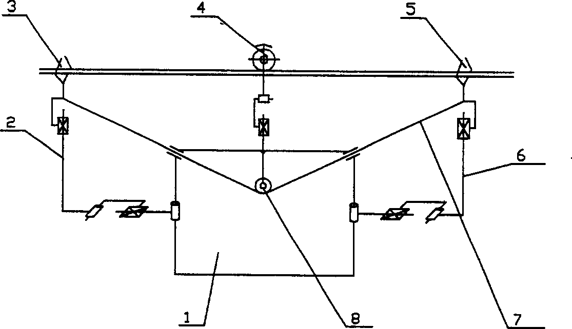
[0024] Such as figure 1 As shown, the mechanical structure of the present invention is made up of body 1, rear arm 2, road wheel 4, front arm 6, soft cable 7 and reel 8, wherein: the mobile car body is made up of body 1 and road wheel 4, and road wheel 4 It is installed on the main body 1 through the horizontal rotating pair and the moving pair, and is grasped with the wire; the main body 1 is connected with the front and rear arms 6 and 2 respectively through the rotating pair, and the end of the arm is a claw; the structure of the front arm 6 and the rear arm 2 The same, each arm is composed of upper arm and lower arm. The upper arm is a combination structure of connecting rod, ball screw and slider. It is connected with the lower arm through a horizontal rotation joint. Any one of them; the front and rear claws 5, 3 can be conventional clamping claw structures, which are respectively grasped with the wire, and the two are connected by the flexible cable 7 wound on the reel ...

Embodiment 2

[0028] Such as Figure 4 As shown, the difference between the mechanism of the present invention and that of Embodiment 1 is that the flexible cable and the reel are removed, and the claws of the two arms become a composite mechanism combining clamping and walking. This mechanism is composed of a driving wheel and a clamping device, namely : the front pawl 5 and the rear pawl 3 are the structures in which a driving wheel is located at the top of the line and a clamping device is located at the bottom of the line, which can walk along the line and grasp the line. The process of walking along the line is the same as in Embodiment 1. During the obstacle-crossing process, the front and rear arms 6 and 2 are stretched out, and the whole machine travels along the line. When the front claw 5 encounters an obstacle, it goes off-line, and the rear claw 3 and the walking wheel 4 drive the mobile car body forward to overcome the obstacle. Afterwards, the drive wheel of front claw 5 hang...

Embodiment 3

[0030] The difference with embodiment 2 is: as Figure 5 Shown, front pawl 5, rear paw 3 are the composite clamping mechanism of traveling wheel combination, promptly a big wheel (be positioned at line top), two small wheels (be positioned at line lower limit) combined structure.


PUM


Abstract

The present invention relates to movable robot mechanism, and is especially ultra high voltage power line polling robot mechanism. The polling robot mechanism consists of moving vehicle, back arm and front arm. The moving vehicle consists of vehicle body and walking wheel, the walking wheel is installed onto the vehicle body via horizontal rotation pair and moving pair and grasps the wire, and the vehicle body is connected via the rotation pair to the front arm and the back arm. The arm has hand claw in the end, the front arm and the back arm have the same structure, and each of the front arm and the back arm consists of two parts, upper arm and lower arm. The upper arm as one combined structure of link rod, ball lead screw and block is connected via horizontal rotation pair to the lower arm; and the lower arm is one great stroke telescopic mechanism. The present invention has great work space, light weight, low power consumption and powerful obstruction crossing capacity.

Description

technical field [0001] The invention relates to a mobile robot mechanism, in particular to an ultra-high voltage transmission line inspection robot mechanism. Background technique [0002] In the existing ultra-high voltage transmission line inspection robot mechanism, most of them adopt the composite mobile mechanism composed of wheeled mobile and composite linkage mechanism (Document 1: Jun Sawada, Kazuyuki Kusumoto, Tadashi Munakata, Yasuhisa Maikawa, Yoshinobu Ishikawa , "AMobile Robot For Inspection of Power Transmission Lines", IEEE Trans.PowerDelivery, 1991, Vol.6, No.1: pp..309-315; Literature 2: Mineo Higuchi, Yoichiro Maeda, Sadahiro Tsutani, Shiro Hagihara, "Development of a Mobile InspectionRobot for Power Transmission Lines", J.of the Robotics Society of Japan, Japan, Vol.9, No.4, pp.457-463, 1991), or a multi-degree-of-freedom system composed of multiple sets of mobile units connected in series Mobile Mechanism (Document 3: Shin-ichi Aoshima, Takeshi Tsujimura...

Claims


Application Information

Patent Timeline
IPC IPC(8): B25J5/02
Inventor 王洪光房立金赵明扬徐志刚曲艳丽
Owner SHENYANG INST OF AUTOMATION - CHINESE ACAD OF SCI
Why Eureka
Try Eureka