Nonthermal plasma air treatment system

An air treatment system and air technology, applied in the direction of gas treatment, separation methods, gasification substances, etc., can solve problems such as complex external mechanisms

Inactive Publication Date: 2005-11-02
ACCESS BUSINESS GRP INT LLC
View PDF0 Cites 14 Cited by
  • Summary
  • Abstract
  • Description
  • Claims
  • Application Information

AI Technical Summary

Problems solved by technology

In order to achieve this function, traditional non-thermal plasma reactors need to include more complicated external mechanisms or self-extinguishing arc mechanisms

Method used


Image

  • Nonthermal plasma air treatment system
  • Nonthermal plasma air treatment system
  • Nonthermal plasma air treatment system

Examples


Embodiment Construction

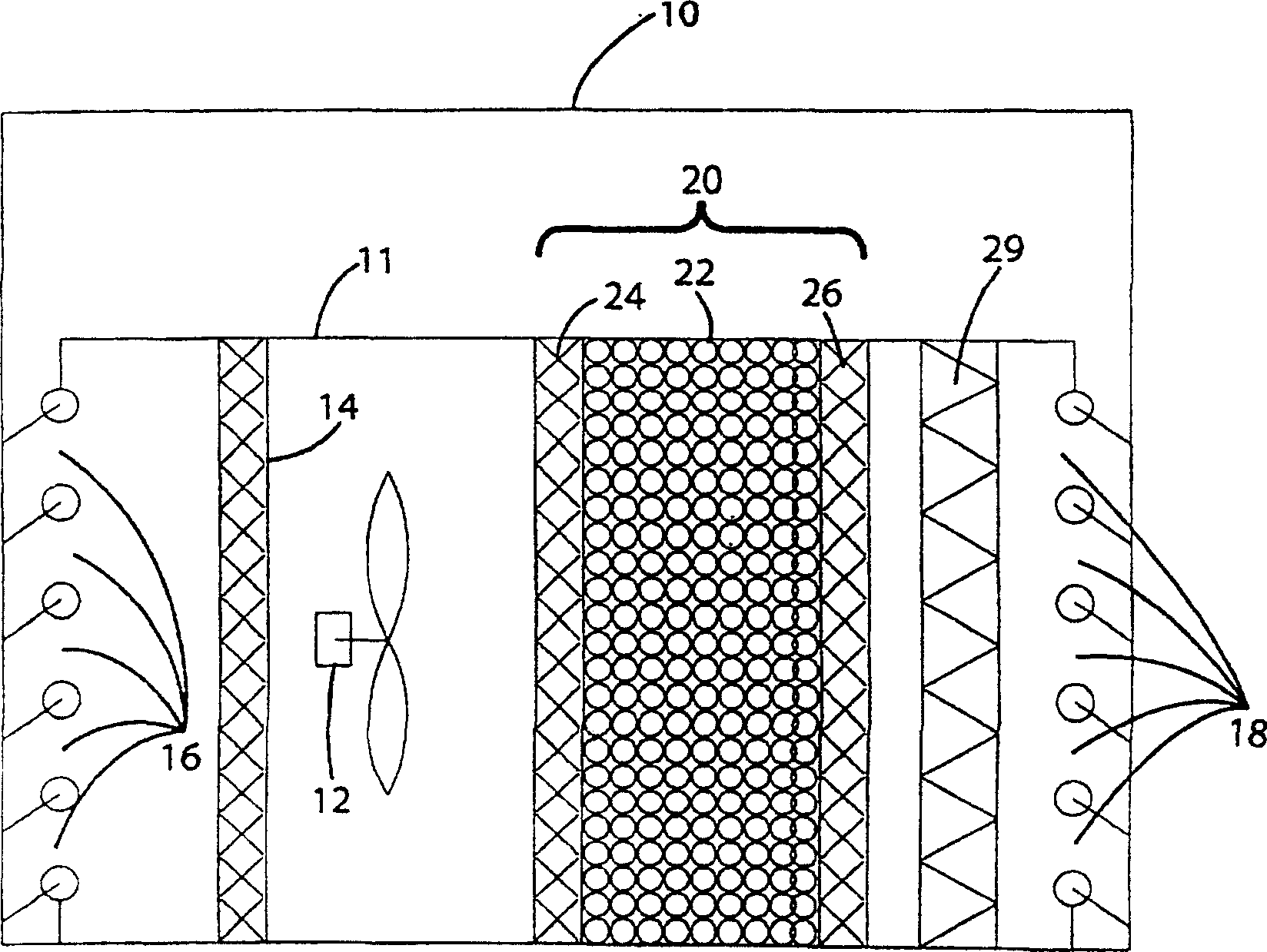
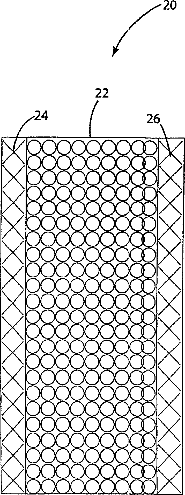
[0039] figure 1 is an embodiment of the present invention. The air treatment system 10 includes a housing 11 and an athermal plasma reactor 20 including a bed of adsorbent material 22 positioned between two opposing electrodes 24 and 26 . Optionally, the air handling system 10 also includes a fan 12 , a set of inlet vanes 16 , a set of outlet vanes 18 , a pre-filter 14 and a HEPA filter 29 .

[0040] A typical operating cycle for air handling system 10 includes two operating phases: an adsorption phase and a desorption / regeneration phase. During the adsorption phase, the vane sets 16 and 18 are turned on and the fan 12 is turned on so that air first passes through the opened vane set 16 and then through the pre-filter 14 into the athermal plasma reactor 20 . Those skilled in the art will appreciate that fan 12 can easily be replaced by a blower or other airflow mechanism known in the art. To provide power to fan 12 and blade sets 16 and 18 using power, power conversion syst...


PUM


Abstract

A method and apparatus for reducing air contamination using a contaminant adsorbent to remove contaminants from air, and a nonthermal plasma to desorb and oxidize or detoxify the contaminants. The adsorbent may be comprised of a unique combination of a zeolite with a material having a high dielectric value. The power supply for the nonthermal plasma reactor is designed to seek and operate at the system resonant frequency. In one embodiment, the adsorbent material is separated from the nonthermal plasma reactor. In this embodiment, heat is applied to the adsorbent material to thermally desorb contaminants during a desorption/regeneration phase. Air is recirculated within the system to move desorbed contaminants from the adsorbent material to the nonthermal plasma reactor for decomposition. The recirculating air repeatedly moves contaminants through the reactor until they are destroyed or the desorption/regeneration phase is complete.

Description

[0001] This application claims priority to US Provisional Application No. 60 / 401665, filed August 7,2002. technical field [0002] The present invention relates to the use of non-thermal plasmas in conjunction with air filtration systems to treat indoor air and reduce pollution. Background technique [0003] Many air purification systems have been described in the literature and are commercially available. These systems use a variety of techniques to remove and sterilize exhaust gases, volatile organic compounds, odors, nitrogen oxides, sulfur oxides, toxic gases, etc., hereinafter referred to as pollutants. These systems utilize various methods to remove airborne pollutants such as combustion, adsorption, catalytic or non-thermal plasma. [0004] The principle of the combustion system is the simplest, which mainly includes heating the air to thermally decompose or burn the pollutants in the air. However, this method is uneconomical because it requires a large amount of en...

Claims


Application Information

Patent Timeline
Patent Type & Authority Applications(China)
IPC IPC(8): A61L9/014A61L9/16A61L9/22B01D53/04B01D53/75
CPCB01D2253/112B01D2253/104B01D53/75A61L9/014B01D2253/102B01D2259/40086B01D2259/40088B01D53/0446B01D53/0454A61L9/16A61L9/22B01D2259/818B01D2253/108A61L9/03
Inventor R·M·泰勒R·W·屈嫩
Owner ACCESS BUSINESS GRP INT LLC
Why Eureka
Try Eureka