
Sintering rear-earth permanent-magnetic alloy and its manufacturing method

A technology of permanent magnets and alloy ingots, applied in the manufacture of inductors/transformers/magnets, magnetic materials, magnetic objects, etc., can solve the problems of reducing the coercive force of the magnets, the magnets cannot be used, and achieves the reduction of remanence and magnetic energy product, Ease of control and improved coercivity

Active Publication Date: 2005-11-09
BEIJING ZHONG KE SAN HUAN HI TECH +1
View PDF1 Cites 4 Cited by
  • Summary
  • Abstract
  • Description
  • Claims
  • Application Information

AI Technical Summary

Problems solved by technology

Although adding a large amount of cheap mixed rare earth alloys (mainly composed of Ce, La) can reduce the remanence of the magnet to a certain extent (see H.R.Madaah Hosseini et al. Journal of Alloys and Compounds.298(2000), 319-323), but The addition of misch metal will reduce the coercive force of the magnet (see J.F.Herbst.Reviews of Modern Physics.Vol.63, No.4, October 1991, 819-904; and F.D.Saccone, H.Sirkin.Physica B: condensed Matter Volume 354.Issues 1-4, 2004, 209-212), resulting in many cases where the magnet cannot be used

Method used


Image

  • Sintering rear-earth permanent-magnetic alloy and its manufacturing method
  • Sintering rear-earth permanent-magnetic alloy and its manufacturing method
  • Sintering rear-earth permanent-magnetic alloy and its manufacturing method

Examples


Embodiment 1

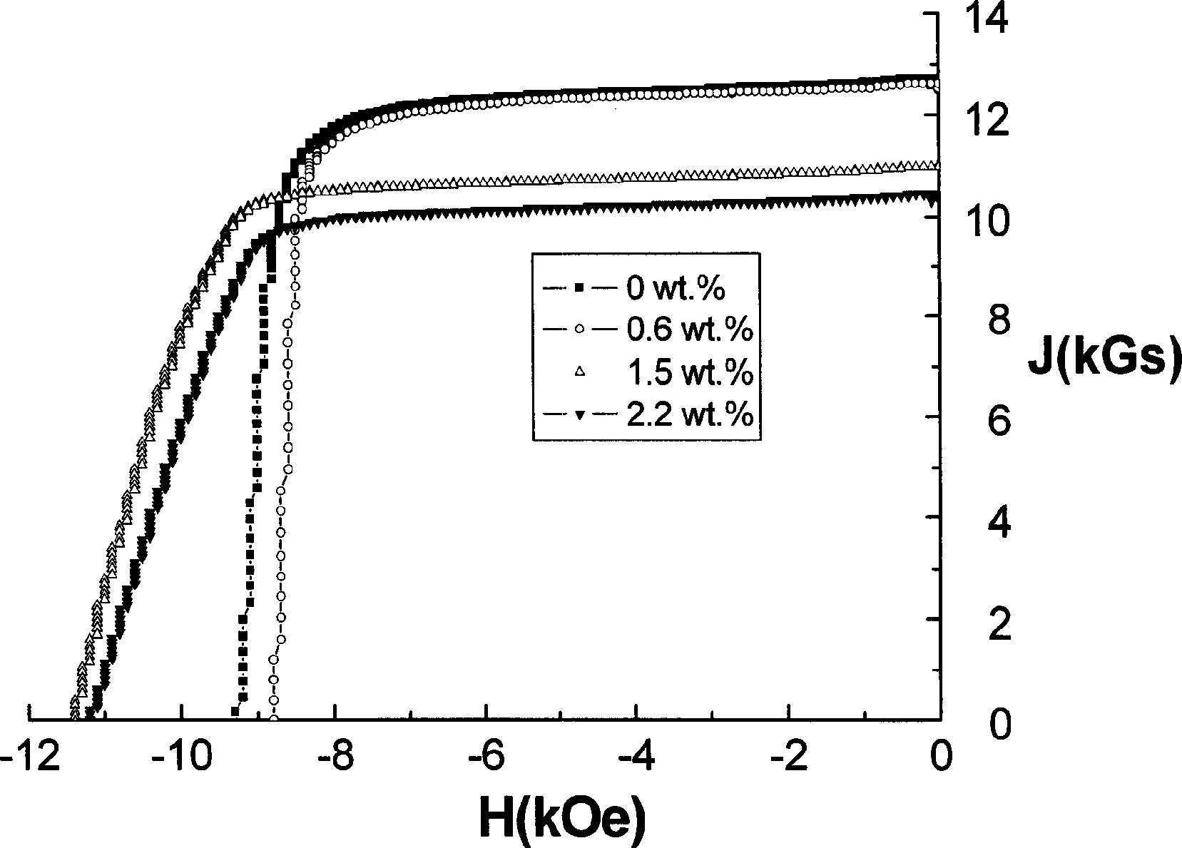
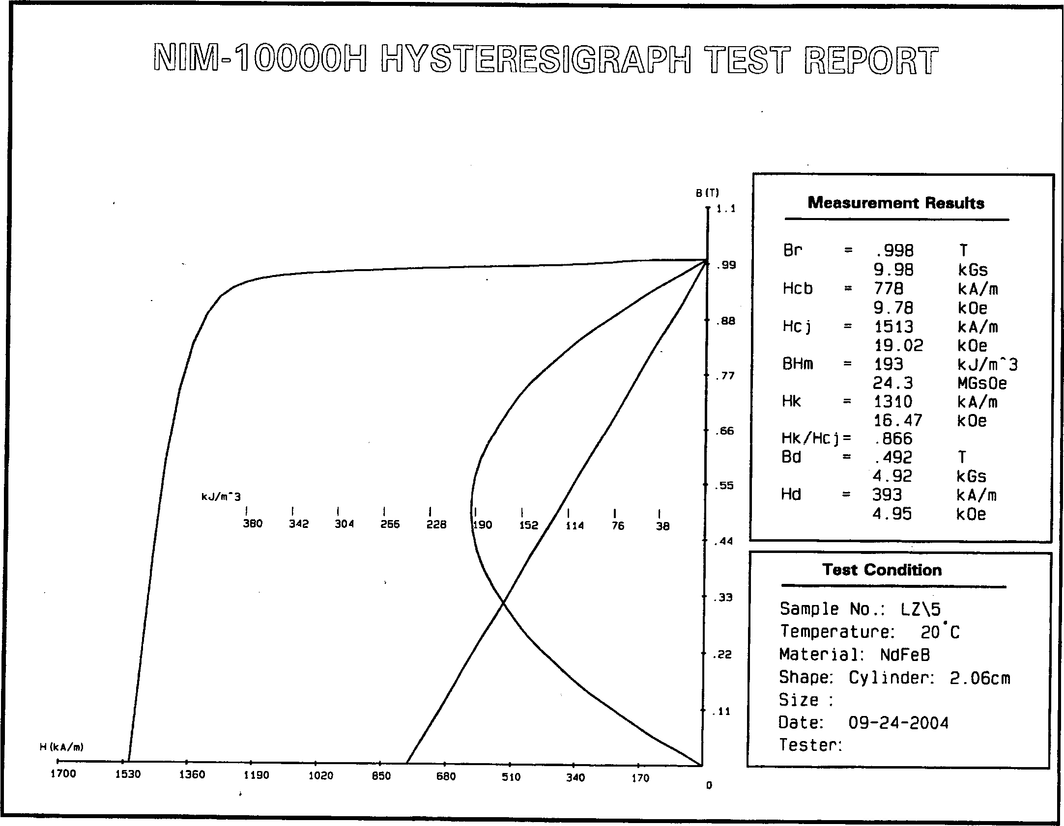
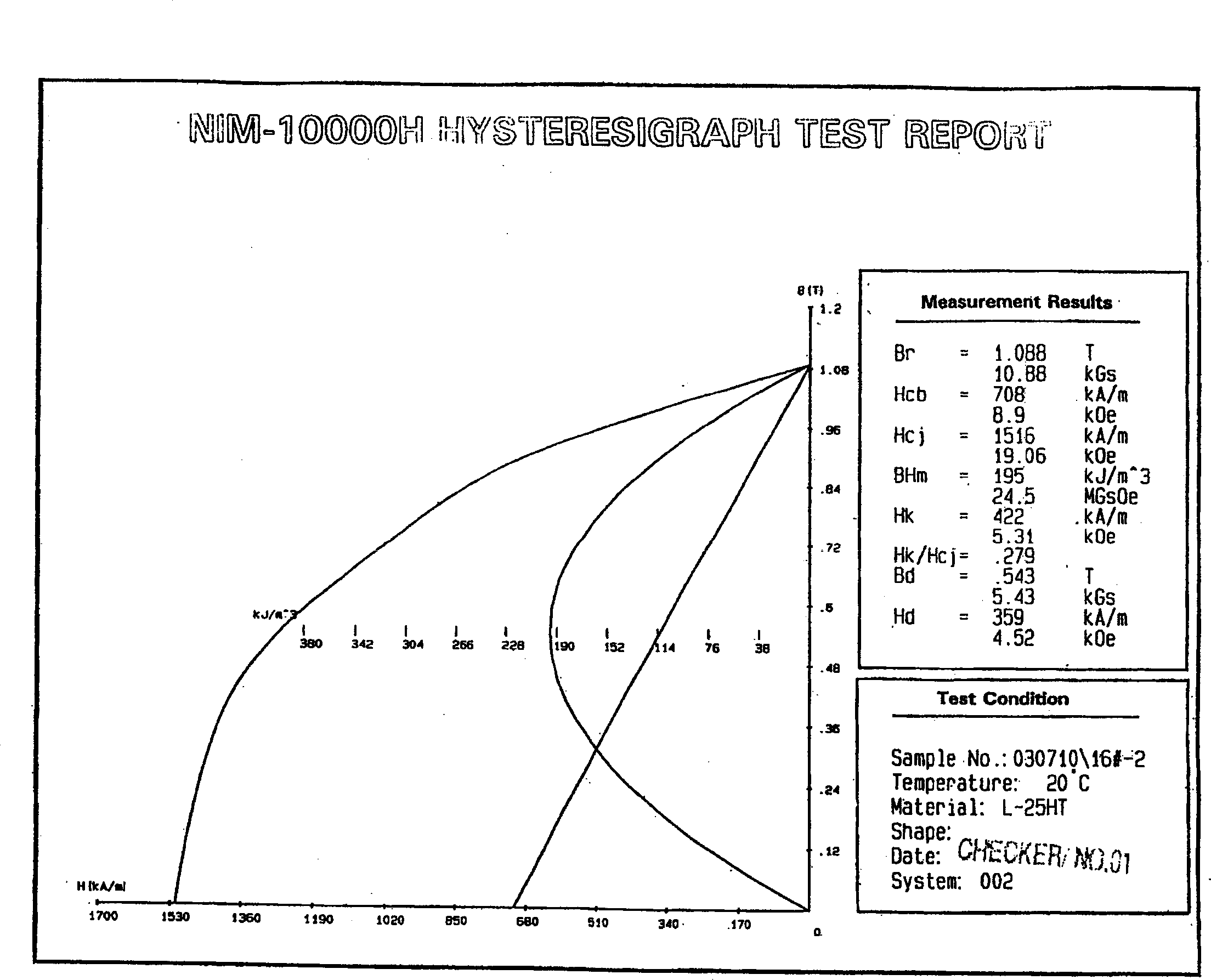
[0039] In this embodiment, a double alloy method is used to manufacture the magnet. The composition of the main alloy is R 14.5 (Fe,TM) 79.5 B 6 (R=Nd, Pr, Dy, Tb; TM=Co, Cu, Al, Nb, etc.) ingot, the secondary alloy is obtained by arc melting, and its composition is R 14.5 (Fe, TM, Cr) 79.5 B 6 (R=Nd, Pr, Dy, Tb; TM=Co, Cu, Al, Nb, etc.). Put them into two stainless steel tanks respectively for hydrogen crushing (HD). After hydrogen crushing, mix the powder according to a certain ratio, then carry out jet milling, orient and shape it under a magnetic field of 2T, and add 200MPa isostatic pressure. The sintering was carried out in a vacuum state at ℃, and the obtained magnet was annealed at 620℃ for 5 hours. Table 1 lists the magnetic properties of magnets with different Cr contents.

[0040] The demagnetization curves of the sintered and annealed magnets were measured using a MagnetPhysik permanent magnet measurement system and a NIM-10000H permanent magnet material mea...

Embodiment 2

[0047] Using the double alloy method, the main alloy is the composition R 14.5 (Fe,TM) 79.5 B 6 (R=Nd, Pr, Dy, Tb; TM=Co, Cu, Al, Nb, etc.) ingot, the secondary alloy is obtained by arc melting, and its composition is R 14.5 (Fe, TM, Mn) 79.5 B 6 (R=Nd, Pr, Dy, Tb; TM=Co, Cu, Al, Nb, etc.). Put them into two stainless steel tanks for hydrogen crushing (HD). After hydrogen crushing, mix the powder according to a certain ratio, then perform jet milling, orient and shape it under a magnetic field of 2T, add 200MPa isostatic pressure, and finally in a vacuum state Carry out sintering. Get the coercive force H cj Magnets greater than or equal to 4kOe, remanence less than 1.1T, and energy product less than 30MGOe.

Embodiment 3

[0049] Using a single alloy method, the composition is R 14.5 (Fe, TM, AF) 79.5 B 6 Ingots of (R=Nd, Pr, Dy, Tb; TM=Co, Cu, Al, Nb; AF=Cr, Mn, etc.). Put it into a stainless steel tank for hydrogen crushing (HD), then jet mill, orient and shape under a magnetic field of 2T, apply 200MPa isostatic pressure, and finally sinter in a vacuum state. A magnet having magnetic properties comparable to Example 1 was obtained.


PUM


Abstract

This invention provides a kind of sintered lanthanon permanent magnet alloy and its manufacturing method. The sintered lanthanon permanent magnet alloy is sintered Nd-Fe-B permanent magnet, including antiferromagnetism transition series element Cr or Mn. Its magnetism performance parameter bounds are: the residual magnetism is no more than 1.1 T, the magnetic energy accumulate is 10 - 30 MGOe, coercive force after anneal heat treatment are no less than 15 kOe. The Nd-Fe-B permanent magnet provided by present invention has such advantages as low cost, good product uniformity, high manufacturing stability, simple manufacturing method, and needn't change the present Nd-Fe-B manufacturing equipments, is easy for controlling and large-scale industrialization manufacturing.

Description

technical field [0001] The invention relates to a sintered Nd-Fe-B permanent magnet, in particular to a sintered Nd-Fe-B permanent magnet with a magnetic energy product ranging from 10 to 30 MGOe and a manufacturing method thereof. Background technique [0002] Since the discovery of Nd-Fe-B in the early 1980s, both the Nd-Fe-B permanent magnet material itself and its application technology have developed rapidly. Nd-Fe-B permanent magnet materials have been widely used in voice coil motors of disk drives, various motors, nuclear magnetic resonance imaging equipment, electroacoustic devices, and magnetic machinery. Nd-Fe-B magnets mainly include sintered Nd-Fe-B and bonded Nd-Fe-B. Remanence B of Nd-Fe-B permanent magnet r and energy product (BH) max It is determined by the following formula: [0003] Br=AfJ s (1-6)d / d 0 [0004] (BH) max =Br 2 / 4μ rec (1) [0005] where A is the volume fraction of the forward domain, f is the degree of orientation, a...

Claims


Application Information

Patent Timeline
Patent Type & Authority Applications(China)
IPC IPC(8): H01F1/08
Inventor 李正何叶青胡伯平王亦忠王震西
Owner BEIJING ZHONG KE SAN HUAN HI TECH
Learn More