Electromagnetic coupling variable-speed drive system

A technology of infinitely variable speed and electromagnetic coupling, which is applied in the direction of electromechanical transmission, control system, electric components, etc., can solve the problems of high manufacturing cost, complex equipment of power confluence and transmission system, etc., and achieve the improvement of overall efficiency and the reduction of rated power capacity , the effect of improving performance

Active Publication Date: 2005-11-09
GUANGZHOU AUTOMOBILE GROUP CO LTD +1
View PDF0 Cites 46 Cited by
  • Summary
  • Abstract
  • Description
  • Claims
  • Application Information

AI Technical Summary

Problems solved by technology

The existing technology has not been able to integrate multiple functions such as power generation, electric drive, engine start, clutch, speed change, and power confluence, so that the power confluence and speed change system equipment is complicated and the manufacturing cost is relatively high.

Method used


Image

  • Electromagnetic coupling variable-speed drive system
  • Electromagnetic coupling variable-speed drive system
  • Electromagnetic coupling variable-speed drive system

Examples


Embodiment 1

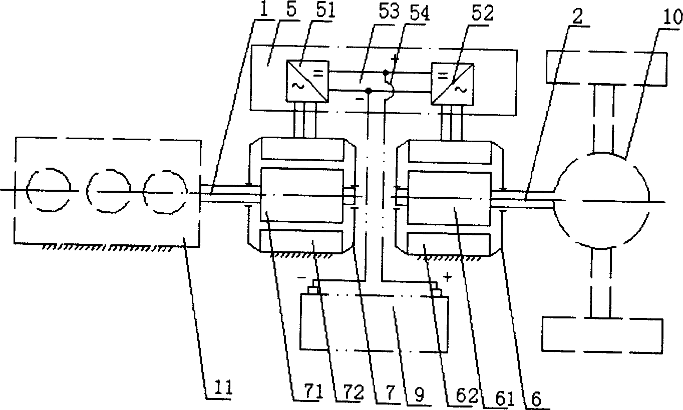
[0027] like Figure 5 As shown, the input shaft 1, the output shaft 2 and the base 3 form a mutual supporting relationship through bearings. The rotor 71 is fixed on the input shaft 1 and placed in the inner cavity of the cup-shaped rotor 67 together with its axial coil winding with an air gap. The cup-shaped rotor 67 is fixedly connected to the output shaft 2 . The stator 62 is fixed on the frame 3 and cooperates with the outer surface of the cup-shaped rotor 67 with an air gap. The additional magnetic modulation coil 4 is a DC coil wound circumferentially in the annular groove of the iron core of the stator 62, and is connected to the power electronic controller 5 through wires. The direction of the current of the additional magnetic modulation coil 4 determines whether the permanent magnet cup rotor 67 is magnetized or weakened, and the magnitude of the current determines the magnitude of this magnetic modulation effect. The induction primary coil 81 and the induction sec...

Embodiment 2

[0032] The prime mover 11 in the first embodiment is connected with the output shaft 2, the load 10 is connected with the input shaft 1, and other structures are completely the same as the first embodiment. In this embodiment, only the input shaft in embodiment 1 is converted into an output shaft, and the output shaft is converted into an input shaft, so that the effect obtained is the same as that in embodiment 1.

Embodiment 3

[0034] The non-contact current collector composed of the induction primary coil 81 and the induction secondary coil 82 in Embodiment 1 is replaced by a conventional contact brush slip ring current collector. This can reduce the cost, weight and system complexity, but the system reliability has decreased.


PUM


Abstract

An electromagnetic couple stepless speed change drive of cars in which the collector and stator are connected with the AC-DC converter and DC-AC conversion inverter in a power electronic controller separately. The input or output shaft is connected with the rotor via the collector, the rotor is set in the cup rotor internal cavity and matched to the cup rotor, one end of which is connected with the output or input shaft, the stator is fixed on the base and matched to the cup rotor. The system combines the cascade electric drive and electromagnetic slippage coupled mechanical drive plus un-contacted rotary transmission to form a power branch collection matched with speed adjustment combining conversion with magnetic adjustment.

Description

technical field [0001] The invention relates to a continuously variable transmission system, in particular to an electromagnetic coupling continuously variable transmission system. The system is applied to traditional vehicles with single prime movers such as thermal engines, oil-electric hybrid electric vehicles, and other mechatronic equipment that require variable speed transmission. Background technique [0002] Various vehicles such as automobiles, as well as many other electromechanical systems, require a power transmission device that can adjust the operating speed to match the load - the transmission. At present, manual or automatic stepped mechanical transmissions based on gear pairs are widely used. Although their own transmission efficiency is high, the quality of speed regulation is not good enough, and the prime mover and load can only be guaranteed at certain points in the system's working range. The correct matching of the system leads to a decrease in the ov...

Claims


Application Information

Patent Timeline
Patent Type & Authority Applications(China)
IPC IPC(8): H02K51/00H02P7/00
Inventor 黄向东罗玉涛赵克刚周斯加杨荣山胡红斐
Owner GUANGZHOU AUTOMOBILE GROUP CO LTD
Why Eureka
Try Eureka