
Coke dry quenching method and system

A technology of dry quenching and coke quenching tower, which is used in furnace safety devices, coke ovens, coke cooling, etc., and can solve the problems of coke floating and scattering.

Inactive Publication Date: 2005-11-09
NIPPON STEEL CORP
View PDF2 Cites 14 Cited by
  • Summary
  • Abstract
  • Description
  • Claims
  • Application Information

AI Technical Summary

Problems solved by technology

[0022] The high-temperature exhaust gas discharged from the coke quenching tower is supplied to the waste heat boiler through the inclined flue part, but if the amount of the exhaust gas exceeds the upper limit flow rate, the phenomenon of coke floating and scattering from the inclined flue part will occur. The sharp increase in the ventilation resistance of the circulating gas is related to the failure of the boiler tube wear caused by the flying coke, so it must be controlled at a certain flow rate or below

Method used


Image

  • Coke dry quenching method and system
  • Coke dry quenching method and system
  • Coke dry quenching method and system

Examples


Embodiment 1

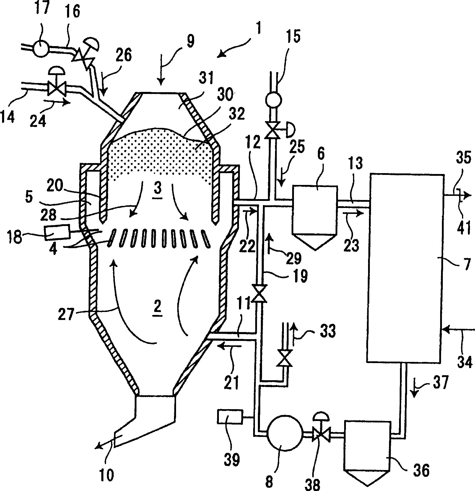
[0184] exist figure 1 The present invention is applicable to the CDQ device shown. The inner volume of cooling chamber 2 of CDQ device is 600m 3 , the inner volume of the prechamber 3 is 300m 3 . The red-hot coke 9 with an average temperature of 980° C. was cooled under the condition of an average discharge rate of 170 tons / hour.

[0185] PC air is blown from the upper part of the pre-chamber into the space 31 formed by the upper surface 30 of red-hot coke and the pre-chamber. In addition, PC water / steam 26 for adjusting the temperature of the pre-chamber is mixed with PC air 24 in the piping of the air blowing device 14, and the mixed gas is blown into the pre-chamber.

[0186] In order to combust combustible components in exhaust gas 22 from coke quenching tower 1 and control components in circulating gas 37 while raising the temperature of exhaust gas, a device for blowing SF air 25 is provided in gas discharge pipe 12 .

[0187] Furthermore, a part of the inert gas su...

Embodiment 2

[0246] exist figure 1 The coke dry quenching device shown is applicable to the present invention. The inner volume of cooling chamber 2 of CDQ device is 600m 3 , the inner volume of the prechamber 3 is 300m 3 . The red-hot coke 9 with an average temperature of 980° C. was cooled under the condition of an average discharge rate of 170 tons / hour.

[0247] As the blowing device 46 for blowing air and water into the prechamber at the same time, it refers to the use of Image 6 In the form shown, two devices are arranged in the pre-chamber. Two blowing devices are arranged at θ=180° along the circumferential direction. As a temperature measurement method in the pre-chamber, radiation thermometers are installed at two places in the inclined flue section, and the temperature of the red-hot coke observed through the annular duct is measured in a non-contact manner, and the temperature measurement results at these two places are used. The average temperature was used as the tempe...


PUM


Abstract

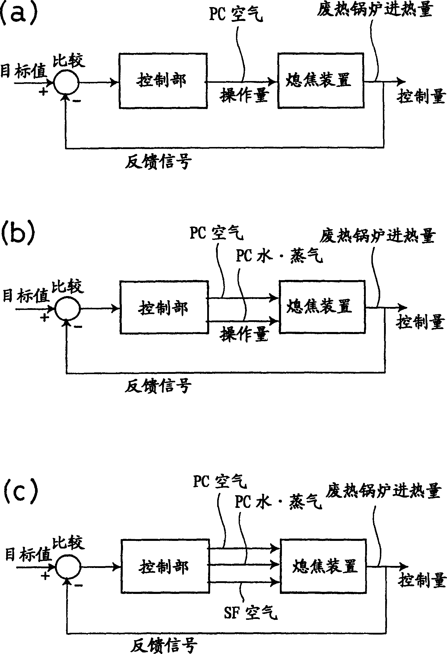
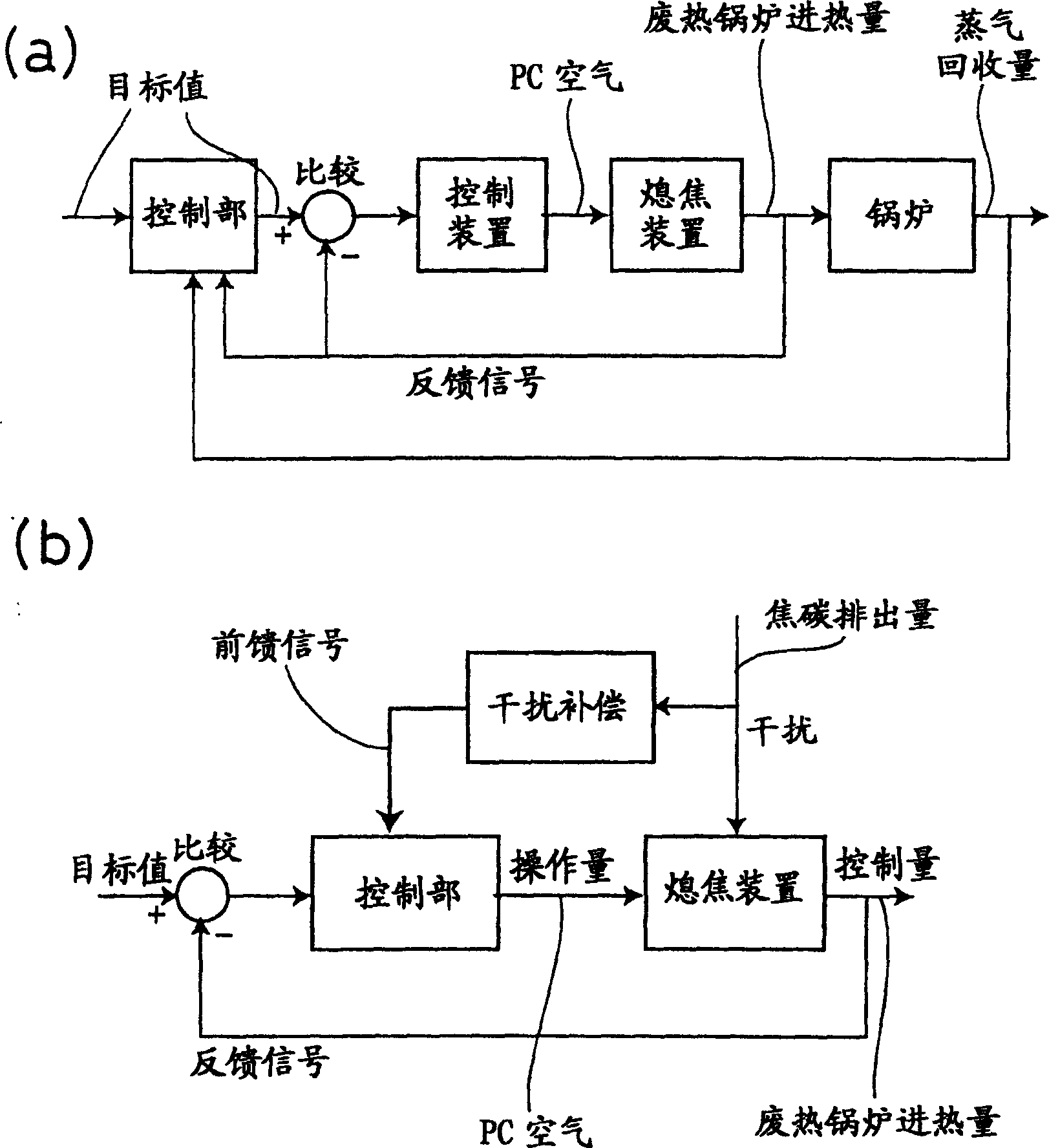
A coke dry quenching method for recovering heat in the form of steam in a waste heat boiler using a quenching column comprising a cooling chamber and a prechamber located above by loading red heat coke from above the prechamber, blowing air and / or water or steam into the prechamber, and exchanging sensible heat of the red heat coke in the cooling chamber using an inert gas as a medium. The quantity of steam being recovered is kept at a constant level by regulating the quantity of air and / or water or steam being blown into the prechamber such that the quantity of heat entering the waste heat boiler has a target level, the quantity of combustible gas component and oxygen component in the circulation gas is kept at a minimum level, adhesion of foreign matters to the sloping flue section is prevented, a heat recovery efficiency is prevented from lowering while protecting the boiler tubes against thermal damage, and the quantity of sensible heat being recovered is maximized while preventing increase of circulation gas ventilation resistance and protecting the boiler tubes against damage due to wear.

Description

technical field [0001] The invention relates to a coke dry quenching method and a flame extinguishing device. Background technique [0002] When cooling the red-hot coke discharged from the coke oven, a coke dry quenching device (so-called CDQ (Coke Dry Quencher)) is used in order to recover the sensible heat of the red-hot coke and save energy. [0003] The dry coke quenching device has a cooling chamber for exchanging sensible heat of red-hot coke with inert gas, and a pre-chamber above the cooling chamber. Red-hot coke is loaded into the pre-chamber from the top of the pre-chamber. The setting of the pre-chamber is for the purpose of absorbing the time fluctuation of red hot coke input and obtaining the stability of operation. [0004] After coke is cooled to around 200°C by heat exchange with inert gas in the cooling chamber, a certain amount is discharged each time. After heat exchange, the inert gas heated to 900°C is discharged from the upper part of the cooling ch...

Claims


Application Information

Patent Timeline
Patent Type & Authority Applications(China)
IPC IPC(8): C10B39/02
CPCC10B39/02Y02P20/129
Inventor 铃木淳紫原康孝横沟正彦
Owner NIPPON STEEL CORP
Learn More