Camshaft regulator

A technology of camshafts and adjusters, applied in machine/engine, valve details, valve devices, etc., can solve problems such as high assembly costs, assembly errors, and large numbers, and achieve the effect of low unit cost and low assembly cost

Active Publication Date: 2005-11-16
SCHAEFFLER TECH AG & CO KG
View PDF2 Cites 10 Cited by
  • Summary
  • Abstract
  • Description
  • Claims
  • Application Information

AI Technical Summary

Problems solved by technology

[0015] The disadvantage that arises in this embodiment is that a large number of parts is required for the thrust bearing of the camshaft
In addition to the higher costs and weight of additional parts this also leads to increased assembly costs
In addition, assembly errors may occur, such as gaskets not being installed inadvertently

Method used


Image

  • Camshaft regulator
  • Camshaft regulator
  • Camshaft regulator

Examples


Embodiment Construction

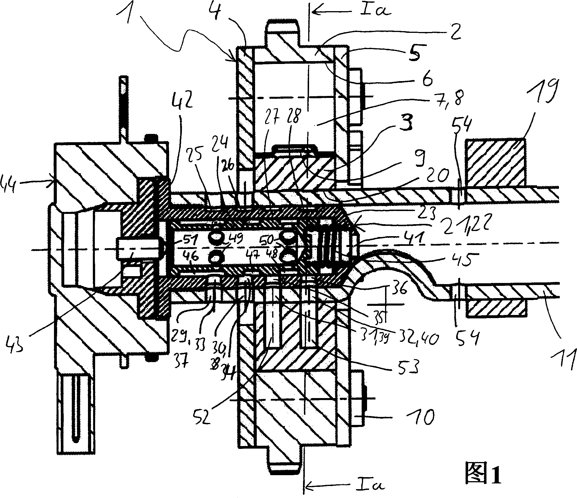
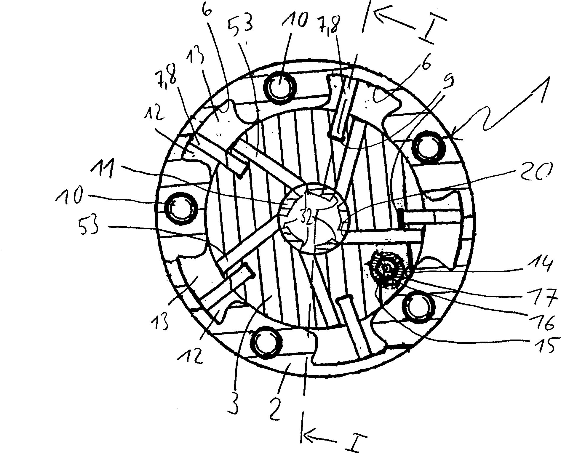
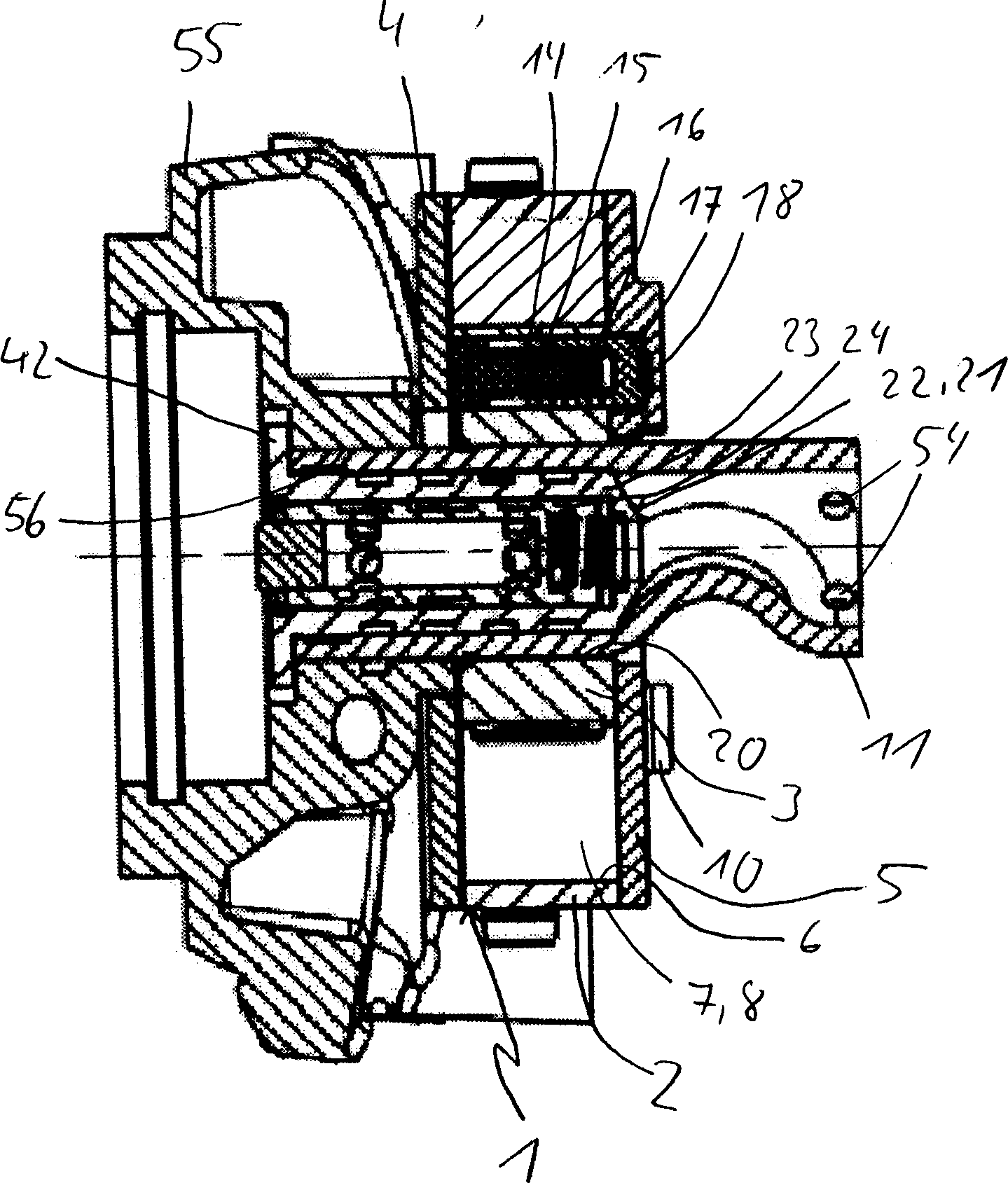
[0031] Figure 1a , 1 to 3 show the device for changing the control timing of the internal combustion engine (camshaft adjuster 1). However, in FIGS. 1 and 1 a the basic construction of the camshaft adjuster 1 is shown in the form of a rotary piston, whereas in FIGS. figure 2 and 3 show two camshaft adjusters according to the invention in different assembly variants. Of course, the hydraulically driven camshaft adjuster 1 can likewise also be of other embodiments, for example an axial piston adjuster. The camshaft adjuster 1 basically comprises a drive wheel 2 , an output part 3 and two disk-shaped side walls 4 and 5 . In the embodiment shown, drive wheel 2 is designed as a sprocket, which is connected to a crankshaft (not shown) via a drive chain. The following embodiment is also possible in that the driving wheel 2 is designed as a belt pulley or a gear, which is driven by a gear belt or a gear transmission of the crankshaft. The drive wheel 2 and the driven part 3 are a...


PUM


Abstract

A device for changing the control times of an internal combustion engine (camshaft adjuster ( 1 )) having a pressure medium distributor ( 21 ) arranged within a camshaft ( 11 ) is provided. The pressure medium distributor ( 21 ) is provided at its front end with a radially extending shoulder ( 42 ), this shoulder ( 42 ) forming part of the camshaft axial mounting.

Description

technical field [0001] The invention relates to a camshaft adjuster for adjusting and fixing the phase of the camshaft of the internal combustion engine relative to the crankshaft of the internal combustion engine, which has a drive wheel driven by the crankshaft, fixed to the driven part of the camshaft, which is mounted on the camshaft or camshaft The extension of the shaft and it is driven by the driving wheel through a hydraulic actuator, wherein the actuator includes at least one pair of interacting hydraulic pressure chambers and wherein the pressure chambers are supplied with pressure oil through a pressure oil distributor and a pressure oil conduit. Background technique [0002] Camshafts are used in internal combustion engines to control the gas exchange valves. The camshaft is installed in the internal combustion engine in such a way that the cams mounted on the camshaft are located next to cam attachments, such as barrel tappets, rocker arms or swing arms. If the...

Claims


Application Information

Patent Timeline
IPC IPC(8): F01L1/04F01L1/34F01L1/344F01L9/10
CPCF01L2001/34433F01L1/34F01L2001/0475F01L1/3442F01L13/00F01L9/00
Inventor 安德烈亚斯·施特劳斯安德烈亚斯·罗尔延斯·霍佩维克托·利希滕瓦尔德约亨·奥克特赖纳·奥特斯巴赫
Owner SCHAEFFLER TECH AG & CO KG
Why Eureka
Try Eureka