
External resonant cavity semiconductor laser and method for manufacturing same

A resonant cavity and laser technology, applied in the field of lasers

Inactive Publication Date: 2005-11-23
ROHM & HAAS ELECTRONICS MATERIALS LLC
View PDF0 Cites 3 Cited by
  • Summary
  • Abstract
  • Description
  • Claims
  • Application Information

AI Technical Summary

Problems solved by technology

That is, this approach uses only one type of tunable laser, rather than many different types of single-mode lasers with separate emission wavelengths, which is generally known to be problematic because it significantly simplifies the overall size of the WDM system , configuration, assembly and maintenance

Method used


Image

  • External resonant cavity semiconductor laser and method for manufacturing same
  • External resonant cavity semiconductor laser and method for manufacturing same
  • External resonant cavity semiconductor laser and method for manufacturing same

Examples


Embodiment

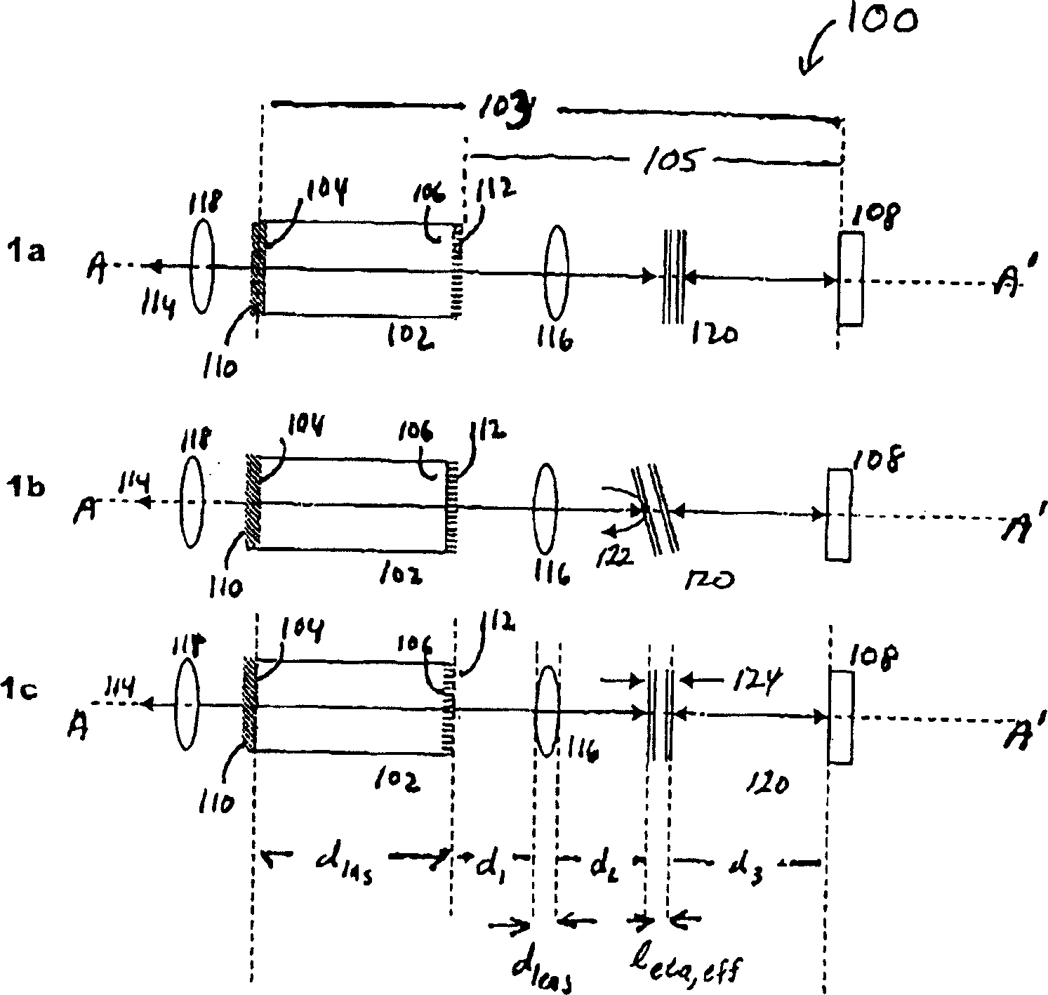
[0071] A notable feature of the present invention is the compactness of the micromachined etalon and the correspondingly shortened optical path length of the optical cavity 103 allows for a simpler method of more optimized mode spacing and mode selection. These aspects of the invention are further exemplified in the following modeled and simulated examples.

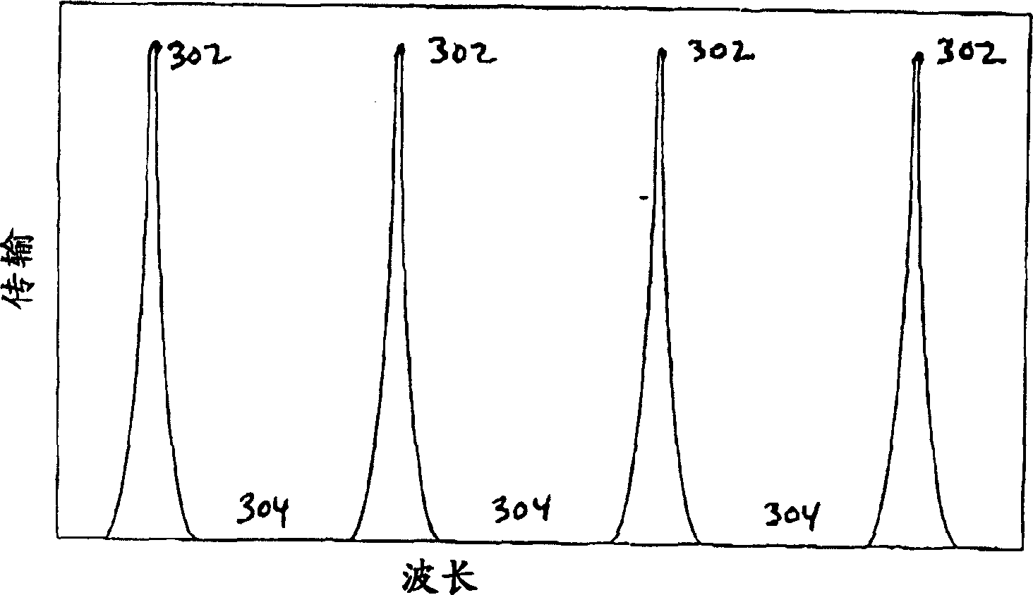
[0072] Figure 8a Shows the effective total optical resonance cavity length l for 24 mm in the spectral range centered at 1550 nm wavelength cav,eff Computational Comb Shapes of Longitudinal Wavelength Modes. The mode spacing is about 0.5 nm. Figure 8b The results of similar simulations for reducing the total optical path length of the laser resonator to 12 mm are shown. It is expected that the mode spacing increases to about 1 nm from that of the first embodiment. Figure 8a and 8b The effect of the length of the optical resonator on the mode spacing is illustrated, and a shorter optical resonator leads to a wider ...


PUM


Abstract

This invention relates to outer resonance chamber single mode laser design, wherein, the short optics path length used in optical resonance chamber provides the single wave choice parts to provide one single mode operation and selective operation mode.

Description

[0001] related application [0002] This application claims U.S. Provisional Application No. 60 / 472914, filed May 23, 2003; U.S. Provisional Application No. 60 / 472873, filed May 23, 2003; and U.S. Provisional Application No. Priority of Application No. 60 / 472692, which is incorporated herein by reference in its entirety. technical field [0003] The present invention generally relates to lasers optically coupled to an external optical resonator, and in particular the invention relates to a laser diode capable of tuning by selecting a specific emission wavelength from a discrete set of emission wavelengths, characterized in that the coupled laser and external optical cavity. More specifically, the present invention relates to microfabricated Fabry-Perot etalons (etalons) for use in external cavity laser systems to select desired lasing modes, demonstrated for use in wavelength division multiplexing (WDM) fiber optic communications system. Background technique [0004] Fibe...

Claims


Application Information

Patent Timeline
IPC IPC(8): H01S5/14
Inventor 大卫·W·沙拉罗辉
Owner ROHM & HAAS ELECTRONICS MATERIALS LLC
Learn More