Eureka AIR delivers breakthrough ideas for toughest innovation challenges, trusted by R&D personnel around the world.

Pressure control valve for hydraulic actuation assembly

A pressure control and component technology, applied in the direction of fluid pressure control without auxiliary power, fluid pressure actuation system components, control valves, etc., can solve the problem of insufficient fluid viscosity

Inactive Publication Date: 2005-11-23
丹拿公司
View PDF0 Cites 0 Cited by
  • Summary
  • Abstract
  • Description
  • Claims
  • Application Information

AI Technical Summary

Problems solved by technology

However, the prior art fails to adequately provide variable pressure control, linear and non-linear, and thermally sensitive compensation for changes in fluid viscosity with temperature

Method used


Image

  • Pressure control valve for hydraulic actuation assembly
  • Pressure control valve for hydraulic actuation assembly
  • Pressure control valve for hydraulic actuation assembly

Examples


Embodiment Construction

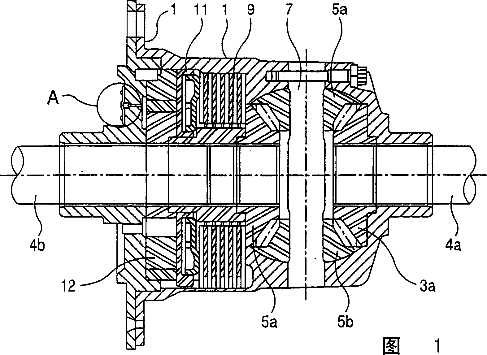
[0019] FIG. 1 is a sectional view of a limited slip differential using a pressure control valve of the present invention. However, it is to be understood that while the present invention is described with respect to a speed sensitive limited slip differential, the present invention is equally applicable to various torque couplings using hydraulic pump systems, and other hydraulic couplings for transmission. A differential case 1 driven by ring teeth (not shown) accommodates a pair of side gears 3a, 3b, a pair of pinion gears 5a, 5b and a pinion shaft 7 to allow for communication between a pair of opposing output shafts 4a, 4b. Speed ​​difference, as generally known in the art. An anti-slip device in the form of a clutch unit 9 is provided between the side gear 3 b and the differential case 1 . A plurality of friction discs are alternately splined to the side gear 3b and the differential case 1 . A hydraulically actuated piston 11 arranged in the piston chamber serves to comp...


PUM


Abstract

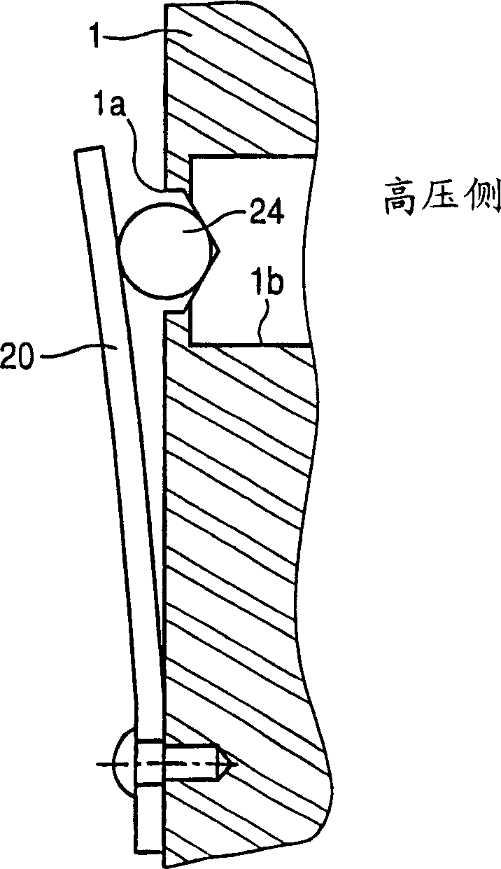
A pressure control valve assembly is disposed in the hydraulic flow path of a differential assembly connected to a passagaway leading to a limited slip device. The assembly includes a blind hole, a groove partially intersecting the blind hole, a ball member seated in the blind hole, and a spring acting on the ball to bias the ball into the blind hole. At the intersection of the blind hole and groove, an area is formed to provide controlled leakage for the hydraulic fuild. As the hydraulic fluid flow increases, the hydraulic pressure of the fluid on the pressure side increases which increases the force on the ball acting against the spring. As the pressure increases further, the resultant forces on the ball deflect the spring to increase the bleed area and increase the fuild bled proportionally to the fluid pressure. Therefore, a pressure control mechanism is provided.

Description

technical field [0001] This invention relates to pressure control valve arrangements in hydraulically actuated differentials or torque couplings used with vehicle transmissions, such as speed sensitive limited slip differentials; A multiple control valve assembly for a hydraulically actuated clutch unit in a connecting device. Background technique [0002] Limited slip differentials and torque couplings are well known in the art. In such an arrangement, a hydraulically actuated friction clutch unit is actuated to inhibit relative rotation of at least one rotating unit, such as at least a side gear, with respect to a differential case. Typically, hydraulic pressure increases directly in response to an increase in differential rotational speed of the shaft components. A common method of providing hydraulic pressure is to include an internal or rotary pump within the differential case. When the hydraulic pressure increases due to the increased speed of the pump (increased sp...

Claims


Application Information

Patent Timeline
IPC IPC(8): F15B21/045F16D25/12F16D48/02F16H48/22F16K15/04F16K17/04G05D16/04
CPCF15B21/045F16K15/046F16D2048/0221F16K17/0406F16D25/12G05D16/04F16D48/02F16D25/14Y10T137/7927
Inventor J·约施奥卡
Owner 丹拿公司
Why Eureka
Eureka Blog
Learn More