Oxonitride phosphor and method for production thereof, and luminescent device using the oxonitride phosphor
An oxynitride and phosphor technology, applied in the field of phosphors, can solve the problems of low luminous brightness, insufficient light-emitting device, difficult processing, etc., and achieve the effect of high luminous brightness and excellent characteristics
- Summary
- Abstract
- Description
- Claims
- Application Information
AI Technical Summary
Problems solved by technology
Method used
Image
Examples
Embodiment approach 1
[0155] Embodiment 1 relates to an oxynitride phosphor suitable for use in combination with a light-emitting element, particularly a nitride semiconductor element. The phosphor is excited by light from a nitride semiconductor light-emitting element and generates light having a wavelength different from that of light from the light-emitting element. .
[0156] The oxynitride phosphor of Embodiment 1 is a phosphor in which a rare earth element is used as an activator and contains an oxynitride phosphor crystal containing at least Be, Mg, Ca, Sr, Ba and at least one group II element selected from the group consisting of Zn and at least one group IV element selected from the group consisting of C, Si, Ge, Sn, Ti, Zr, and Hf .
[0157] Here, the oxynitride phosphor crystal is, for example, an oxynitride phosphor composed of an orthorhombic crystal as shown in Examples described later.
[0158] The combination of the aforementioned group II elements and group IV elements is optiona...
Embodiment approach 2
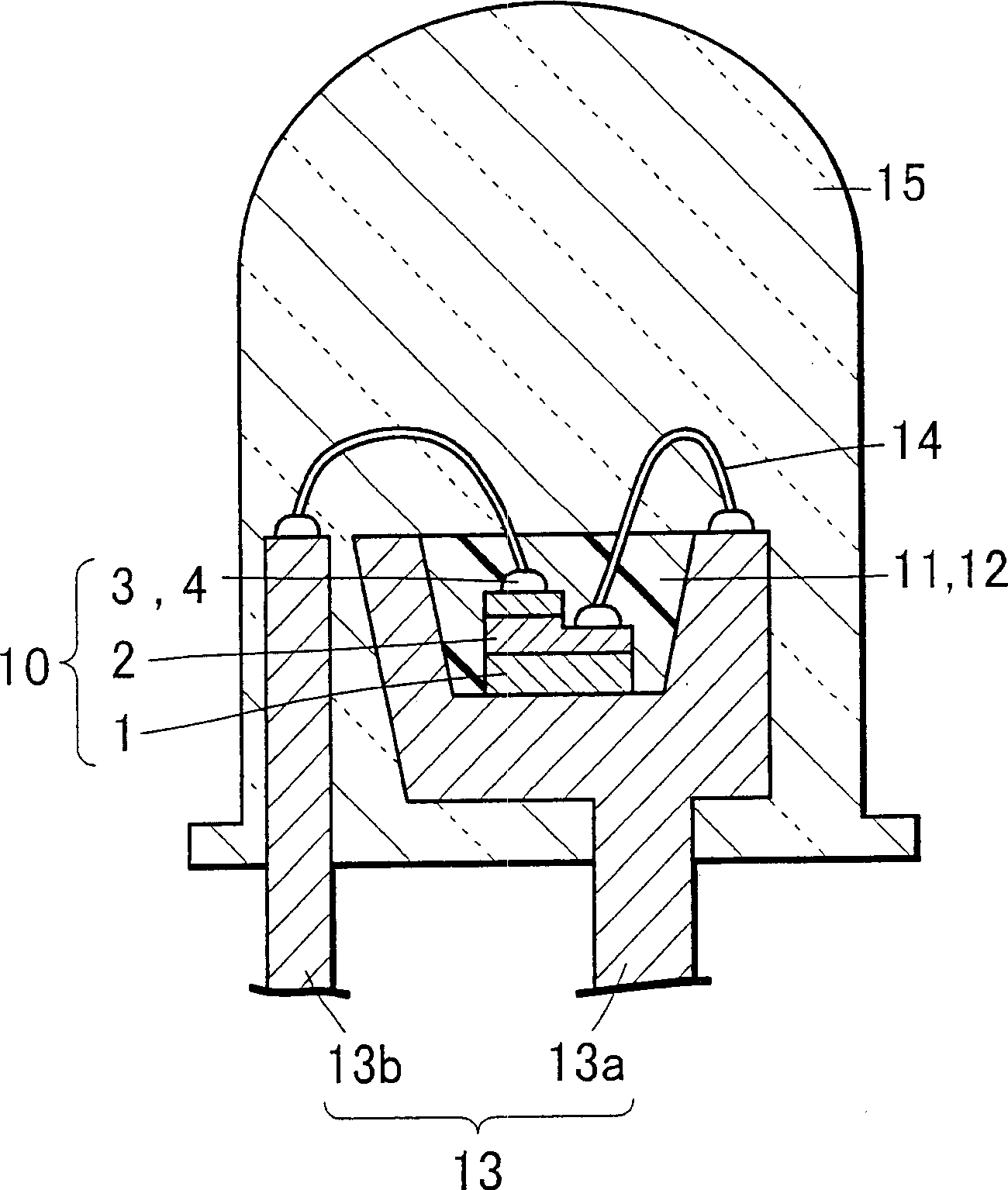
[0218] figure 1 It is a cross-sectional view showing the configuration of a light emitting device according to Embodiment 2 of the present invention. The light emitting device of the present invention includes at least a light emitting element and a first phosphor that converts the wavelength of at least part of light from the light emitting element. Here, particularly in the light-emitting device of the second embodiment, the oxynitride phosphor of the first embodiment is used as the first phosphor.
[0219] In addition, in this specification, the relationship of a color name and a chromaticity coordinate refers to JIS Z8110.
[0220] In the light-emitting device of Embodiment 2, the light-emitting element 10 is composed of a sapphire substrate 1 , a semiconductor layer 2 formed on the sapphire substrate 1 , and positive and negative electrodes formed on the semiconductor layer 2 . The light-emitting element 10 is bonded in a cup of a lead frame 13a, and its positive and neg...
Embodiment approach 3
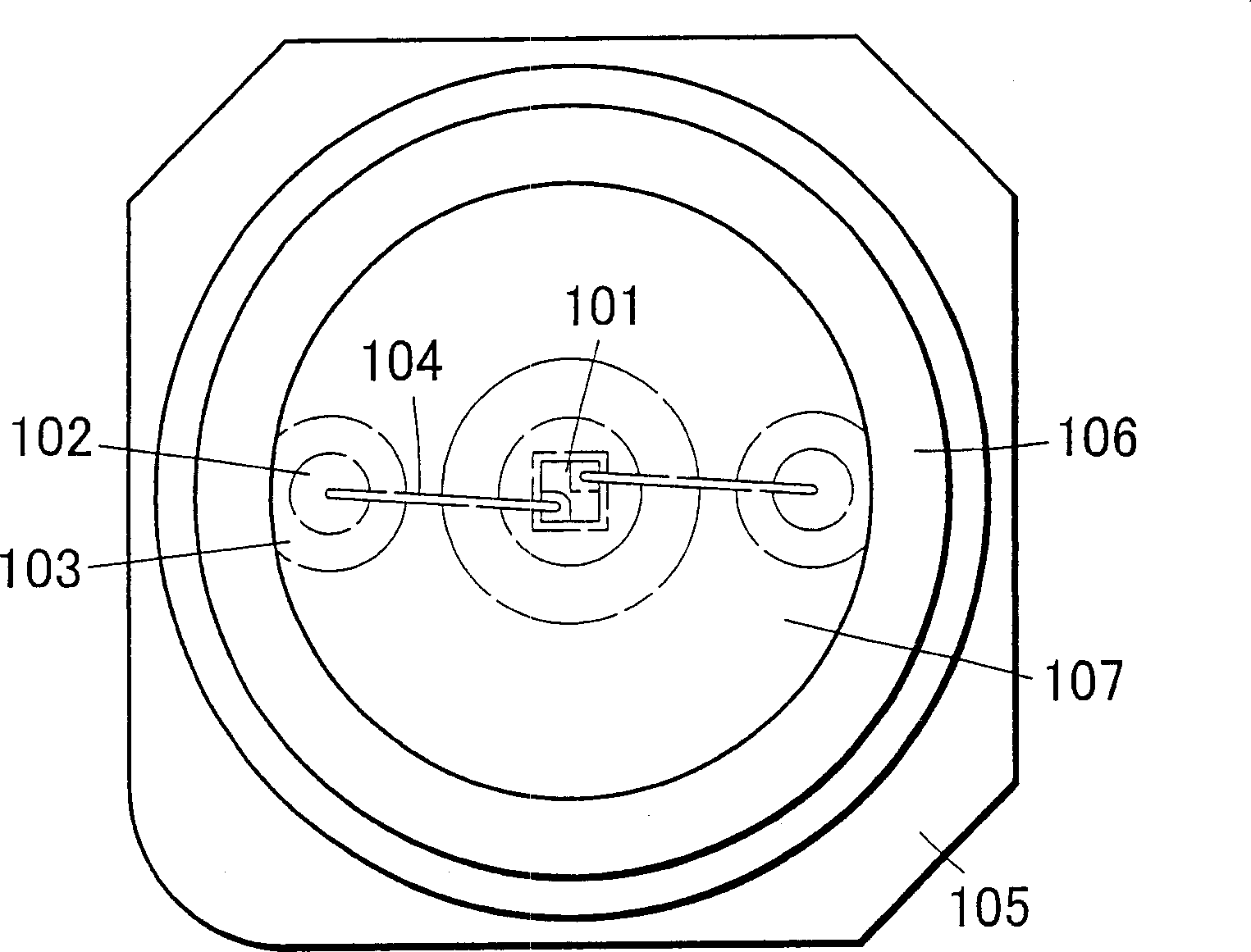
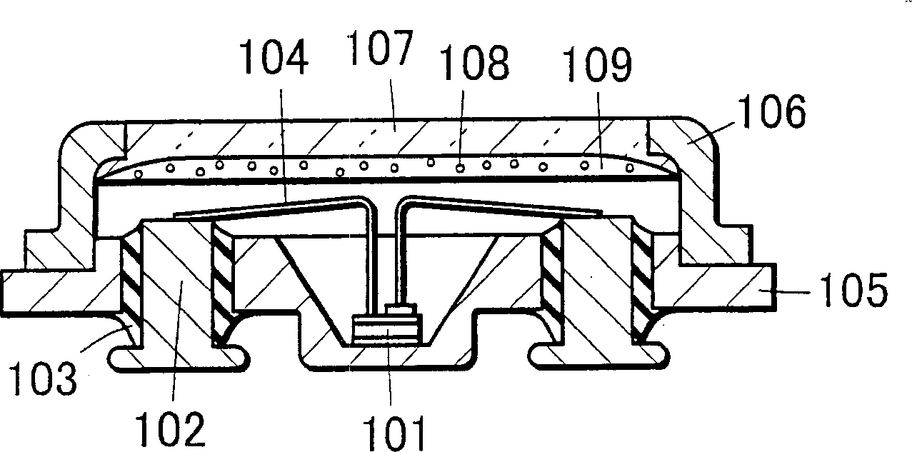
[0271] 2 is a plan view showing the configuration of a light emitting device according to Embodiment 3 of the present invention ( Figure 2A ) and section view ( Figure 2B ). The light emitting device according to Embodiment 3 is a surface mount type light emitting device. In the light emitting device according to Embodiment 3, as the light emitting element 101 , a nitride semiconductor light emitting element emitting light in an ultraviolet region or a nitride semiconductor light emitting element emitting light in a blue region can be used. In addition, the specific configuration is the same as that of the light emitting element of the second embodiment.
[0272] Here, the light-emitting element 101 that emits light in the ultraviolet region will be described as an example. In Embodiment 3, the light emitting element 101 is a nitride semiconductor light emitting element having an InGaN semiconductor having a light emission peak wavelength of about 370 nm as a light emitti...
PUM
| Property | Measurement | Unit |
|---|---|---|
| The average particle size | aaaaa | aaaaa |
| Particle size | aaaaa | aaaaa |
| Particle size | aaaaa | aaaaa |
Abstract
Description
Claims
Application Information
 - R&D
- Intellectual Property
- Life Sciences
- Materials
- Tech Scout
- Unparalleled Data Quality
- Higher Quality Content
- 60% Fewer Hallucinations
Browse by: Latest US Patents, China's latest patents, Technical Efficacy Thesaurus, Application Domain, Technology Topic, Popular Technical Reports.
© 2025 PatSnap. All rights reserved.Legal|Privacy policy|Modern Slavery Act Transparency Statement|Sitemap|About US| Contact US: help@patsnap.com


