
Method for producing biomass carbonized gas and back fire-biomass carbonated gas generating stove

A biomass charcoal and gas generation technology, which is used in biofuels, coke ovens, special forms of dry distillation, etc. to prevent soil erosion, alleviate water shortages, and save energy.

Inactive Publication Date: 2005-12-21
韩连恩 +1
View PDF0 Cites 17 Cited by
  • Summary
  • Abstract
  • Description
  • Claims
  • Application Information

AI Technical Summary

Problems solved by technology

[0002] In the prior art, it has not been found that agricultural and forestry waste such as biomass stalks, branches, rice husks, and fruit shells are separately set in the same furnace to produce biomass gas and biomass charcoal in the upper backfire gasification furnace chamber and the lower carbonization furnace chamber. Method and counterfire biomass carbonization gas generator

Method used


Image

  • Method for producing biomass carbonized gas and back fire-biomass carbonated gas generating stove

Examples


Embodiment 1

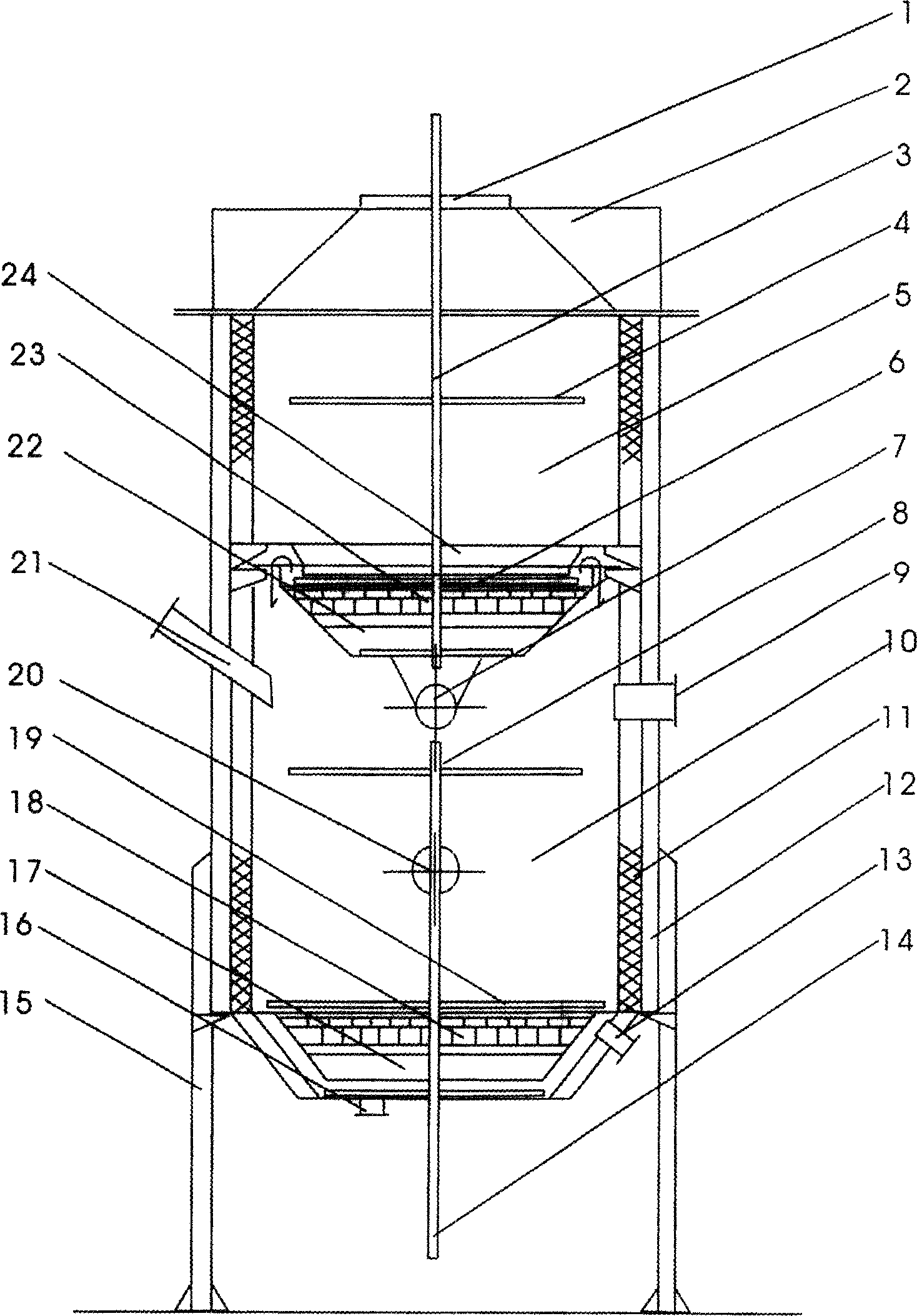
[0020] Using corn stalks and sorghum stalks as the main raw materials, after being chopped according to the above process, the dust and waste materials that do not meet the requirements for carbonization materials are screened and removed, and then the moisture content is controlled at 15% after drying and dehydration. Put into the lower carbonization furnace cavity 10 in the above-mentioned furnace with a height of 8.9 meters and an inner diameter of 3 meters, and add the undersieve straw fines and other agricultural and forestry wastes that are not suitable for carbonization materials into the upper layer of the furnace for gasification after processing. Ignite in the furnace chamber 5, start the suction fan to suck the air (gasification agent) from the furnace upper feeding port 1 into the furnace upper backfire gasification furnace chamber 5 and perform gasification reaction with the gasification material to generate 300-500°C The combustible gas is sucked out of the furnac...

Embodiment 2

[0023] Using branches and cotton stalks as the main raw materials, after chopping according to the above process, screen and remove the dust and waste materials that do not meet the requirements for carbonization materials, and then dry and dehydrate, control the moisture content at 15%, and then add high 9.6 In the lower carbonization chamber 10 of the above-mentioned furnace with an inner diameter of 3.6 meters, the above-mentioned undersieves, branches, cotton stalks and other fine materials and other agricultural and forestry wastes that are not suitable for carbonization materials are added to the upper layer of the furnace after processing. Fire is ignited in the gasification furnace chamber 5, and the suction fan is started to suck the air (gasification agent) into the upper backfire gasification chamber 5 of the furnace from the charging port 1 on the furnace to carry out the gasification process with the gasification material in the gasification furnace chamber. The ga...


PUM


Abstract

Its craft steps are: respectively cut material into pieces, comminute, and filtrate, add material unsuitable to produce carbonization into the upper layer converse fire gasifying stove cavity as its gasifying fuel; add gasifying material suitable for producing biomass charcoal into the carbonizing stove cavity equipped on the nether layer; produce biomass fuel gas and get biomass carbonized products. Its main structure is: there equips upper layer converse fire gasifying stove cavity and nether layer carbonizing stove cavity in the stove body. Its advantages are: its biomass carbonized fuel gas value can get to 5000 - 6000 KJ / h, add the produced biomass charcoal into water-soluble macromolecule cementing agent after comminuted to process into machine-made charcoal by mechanism extrusion; it can replace the carbonized produces of previous wood charcoal; its structure is simple and reasonable, and is convenient to operate; besides its processing material quantity is large, carbonization speed in stove is high and its efficiency is high.

Description

technical field [0001] The present invention relates to a method for producing biomass gas and biomass charcoal in the upper reverse fire gasification furnace chamber and the lower carbonization furnace chamber which separate agricultural and forestry wastes such as biomass straw, branches, rice husks and fruit shells in the same furnace. The method and the counterfire biomass carbonization gas generator. The invention belongs to the technical field of an anti-fire biomass carbonization gas generator. Background technique [0002] In the prior art, it has not been found that agricultural and forestry waste such as biomass stalks, branches, rice husks, and fruit shells are separately set in the same furnace to produce biomass gas and biomass charcoal in the upper backfire gasification furnace chamber and the lower carbonization furnace chamber. The method and the counterfire biomass carbonization gas generator. Contents of the invention [0003] The object of the present ...

Claims


Application Information

Patent Timeline
IPC IPC(8): C10B53/02
CPCY02E50/10
Inventor 韩连恩张连发
Owner 韩连恩
Learn More