
External cavity multiple wavelength laser system

一种激光系统、波长的技术,应用在激光系统领域,能够解决大功率蓝色激光低再结合效率、很难获得、设备昂贵等问题

Inactive Publication Date: 2005-12-21
SAMSUNG ELECTRONICS CO LTD
View PDF4 Cites 10 Cited by
  • Summary
  • Abstract
  • Description
  • Claims
  • Application Information

AI Technical Summary

Problems solved by technology

As far as the inventors know, there is no semiconductor laser that can emit both blue wavelength and green wavelength light
[0003] Diode-stimulated solid-state (DPSS) lasers combined with second-harmonic generation (SHG) technology can provide green laser light at 532 nm, but such equipment is currently relatively expensive
High-power blue lasers are difficult to obtain due to their low recombination efficiency

Method used

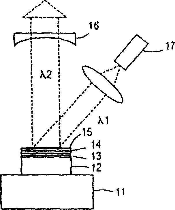
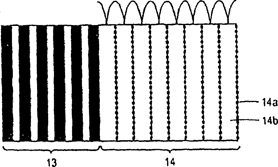
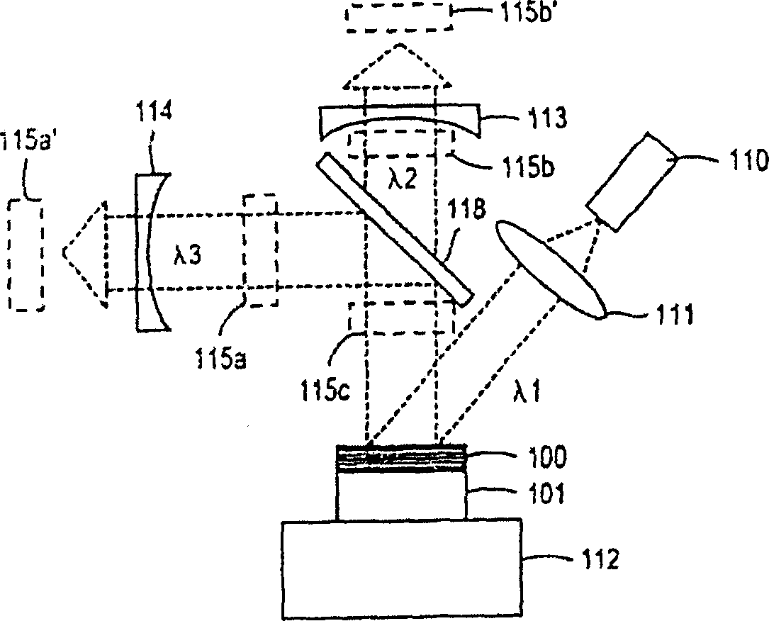

Image

  • External cavity multiple wavelength laser system
  • External cavity multiple wavelength laser system
  • External cavity multiple wavelength laser system

Examples


Embodiment Construction

[0023] image 3 An example of a vertical external cavity surface emitting laser (VECSEL) is briefly shown. The basic vertical external cavity surface emitting laser has a well-known lasing structure, which includes an active region for lasing, and an upper semiconductor layer and a lower semiconductor layer in which the active region is located, but the basic structure has Many styles. The present invention is not limited to this particular structure, but is applicable to various lasing structures including multiple quantum wells.

[0024] Such as image 3 As shown, the laser using the optical excitation scheme includes an excitation laser diode 110 , which projects a parallel beam of excitation wavelength λ1 onto the laser excitation structure 100 through a collimating lens sheet 111 . The excitation light does not have to originate from the diode, nor does it have to be coherent light. The laser excitation component is formed on the substrate 101 , and the substrate is p...


PUM


Abstract

Controlling the number and type of quantum wells in a multilayer gain member of an external cavity surface emitting laser can provide output of light at more than one coherent optical wavelength. The number and type of layers in the multilayer mirror structure can provide a dual wavelength reflector.

Description

technical field [0001] The present invention relates to a laser system capable of emitting two or more coherent wavelengths, in particular to two types of semiconductor vertical external cavity surface-emitting lasers with optional position quantum wells (optical pump) and electrical pump (electrical pump) (VECSEL), the quantum well is used to control the power of each said wavelength of light. Background technique [0002] The demand for multi-wavelength laser sources is increasing. For example, the proliferation of multiple laser display devices presents a need for red (R) (~625 nm), green (G) (~532 nm) and blue (B) (~460 nm) colored laser sources. As far as the present inventors are aware, there is no semiconductor laser that emits light at both blue and green wavelengths. [0003] Diode-stimulated solid-state (DPSS) lasers combined with second-harmonic generation (SHG) technology can provide 532-nanometer green laser light, but such equipment is currently relatively ex...

Claims


Application Information

Patent Timeline
Patent Type & Authority Applications(China)
IPC IPC(8): H01S3/091H01S3/0941H01S3/10H01S5/024H01S5/04H01S5/06H01S5/14H01S5/183H01S5/343
CPCB82Y20/00H01S3/09415H01S3/109H01S5/024H01S5/041H01S5/1096H01S5/141H01S5/146H01S5/18383H01S5/34313H01S5/183
Inventor 金泽
Owner SAMSUNG ELECTRONICS CO LTD
Learn More