Laser receiving and echo device

A laser receiving and echo technology, applied in the field of applied optics, can solve the problems of large loss of light energy, loss of light energy, loss of light, etc.

Inactive Publication Date: 2005-12-21
UNIV OF ELECTRONIC SCI & TECH OF CHINA
View PDF0 Cites 6 Cited by
  • Summary
  • Abstract
  • Description
  • Claims
  • Application Information

AI Technical Summary

Problems solved by technology

The disadvantage of this scheme is that the light energy loss is large and the system structure is more complicated.
Because this system requires 5 convex lenses and a right-angle prism, from the perspective of energy loss, since th

Method used


Image

  • Laser receiving and echo device
  • Laser receiving and echo device
  • Laser receiving and echo device

Examples


Embodiment Construction

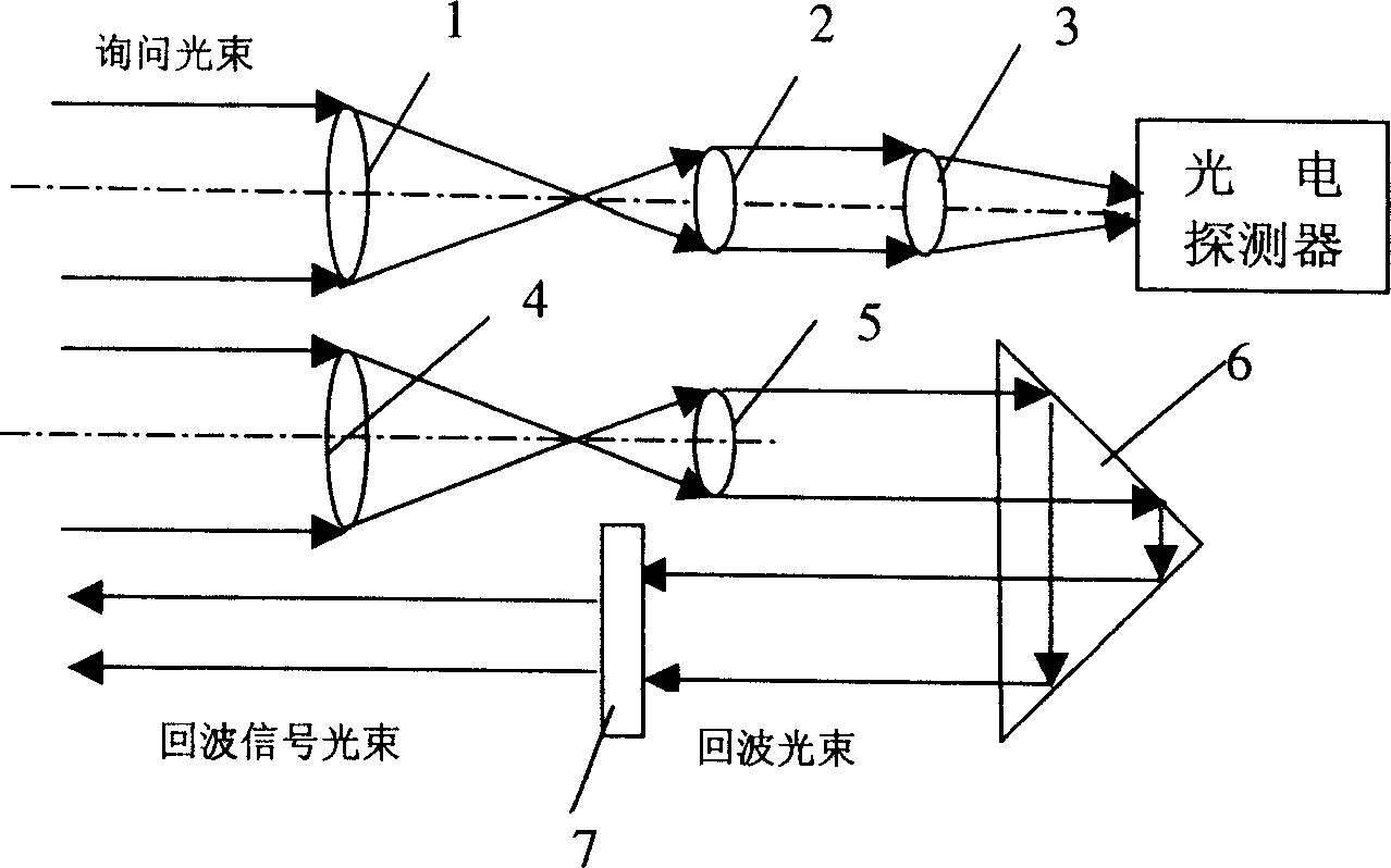
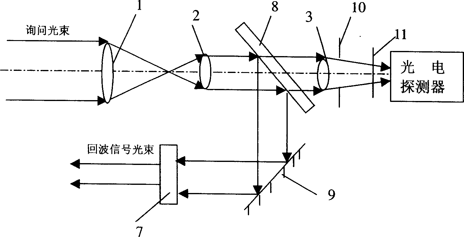
[0039] The whole laser receiving and echo device such as figure 2 As shown, its composition and positional relationship are the same as those in the technical solution of the summary of the invention, and will not be described in detail here.

[0040] The transmittances of the three convex lenses are all over 99%, the diameters of the lens 2 and the lens 3 are 1 cm, the reflectance of the beam splitter is 95%, and the projection rate is 5%. The caliber of lens 1 can be determined according to the peak power of the interrogation light emitted by the interrogator and the distance of recognition. When the peak power P=15W of the interrogation light sent by the interrogator, the visibility of the atmosphere is 15Km, and the loss coefficient is α=0.2. Optical transmittance τ of the system t =0.95, the optical transmittance of the receiving system is τ r =0.98, when the communication and recognition distance Z=500m~1000m, the aperture of lens 1 can be taken as d=6cm, that is, the...


PUM

PropertyMeasurementUnit
Caliberaaaaaaaaaa

Abstract

The disclosed device is composed of three pieces of convex lens, one beam splitting plate, and one plane reflector. The said three pieces of convex are placed in parallel and their central lines are coincident. Passing through lens 1 and being received by lens 2, the inquiring light becomes a narrow beam, which is divided by the beam splitting plate into transmitted light and reflected light. The transmitted light reaches to detector in electrooptical signal conversion and information processing part of receiver. Reflected by the plane reflector, reflected light forms an echo wave, which is returned parallel to direction of the inquiring light. May added into the device, diaphragm and filter carries out filtering for inquiring light in space and frequency in order to reduce stray light and noise generated from background radiation. Thus, detecting SNR of answering party is raised. Modulator added modulates echo wave. Features are: small wastage, simple structure, raised SNR etc.

Description

technical field [0001] The invention belongs to the technical field of applied optics, and in particular relates to a laser receiving and echo device in laser communication or target recognition. Background technique [0002] Laser communication is a communication method that uses laser beams as a carrier for communication. The basic laser communication system consists of a transmitter (interrogator), a receiver (responder) and a space atmospheric channel. Laser target recognition is essentially a kind of laser communication under certain conditions. The basic laser target recognition system is also composed of a transmitter (interrogator), a receiver (responder) and a space atmospheric channel. In laser communication or laser target recognition, after the interrogation beam sent by the inquiring party is received by the receiving antenna (usually a receiving device composed of optical lenses) of the responding party, the interrogating beam needs to be divided into two part...

Claims


Application Information

Patent Timeline
IPC IPC(8): H04B10/67
Inventor 杨亚培张向前谢康饶建珍戴基智刘永智
Owner UNIV OF ELECTRONIC SCI & TECH OF CHINA
Why Eureka
Try Eureka