
Work condition analogue rolling contact fatigue tester

A rolling contact fatigue and working condition simulation technology, which is used in material inspection products, testing wear resistance, and using mechanical devices to achieve the effect of shortening fatigue test time and fast fatigue wear test.

Inactive Publication Date: 2006-01-04
YANSHAN UNIV
View PDF2 Cites 48 Cited by
  • Summary
  • Abstract
  • Description
  • Claims
  • Application Information

AI Technical Summary

Problems solved by technology

The above two testing machines do not have the function of capturing the instantaneous state of fatigue microcrack failure, gluing failure and wear failure of the friction pair surface during the test; there is no function of simulating the actual working condition lubrication state, working condition temperature, working condition load, etc.

Method used

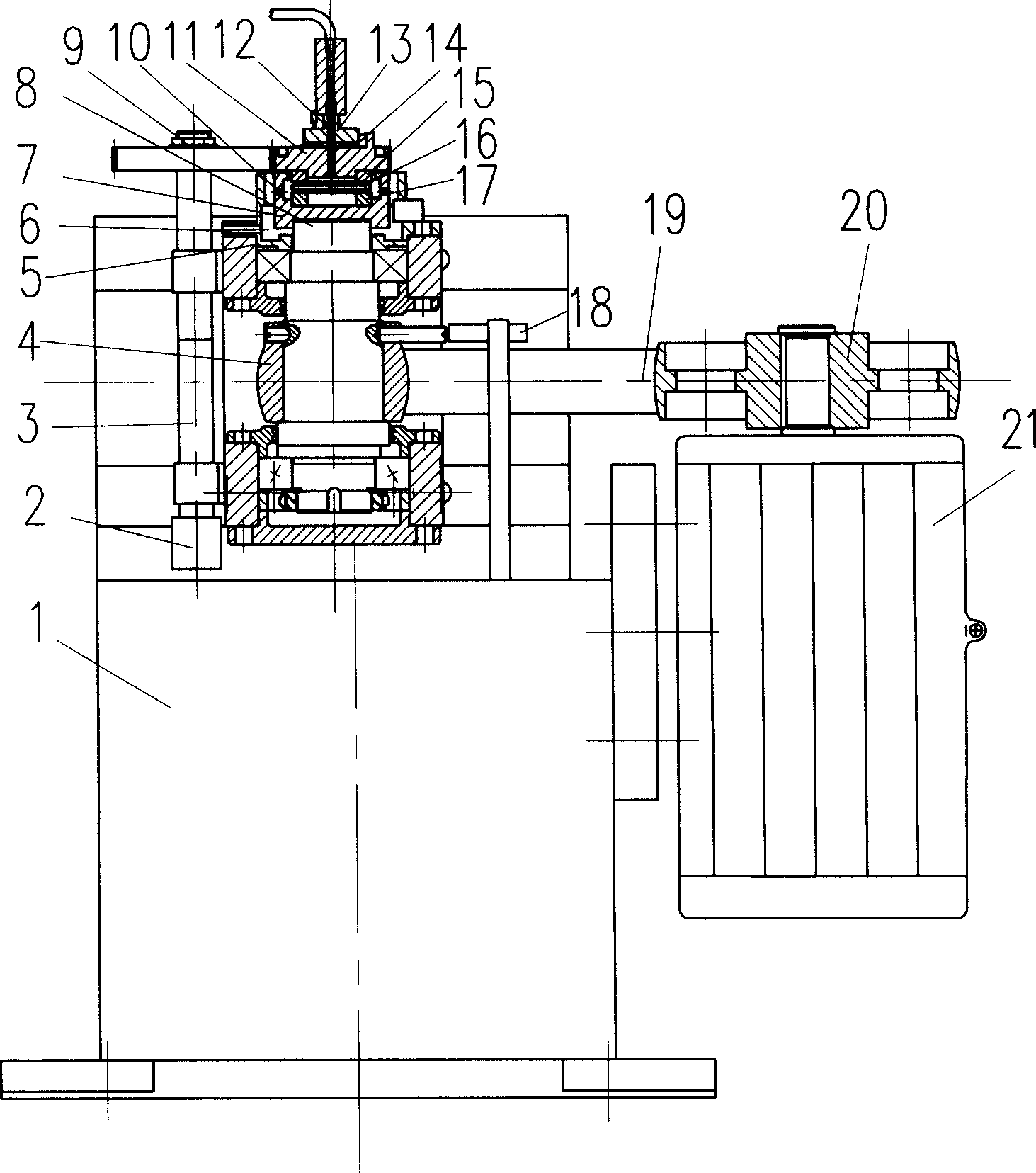
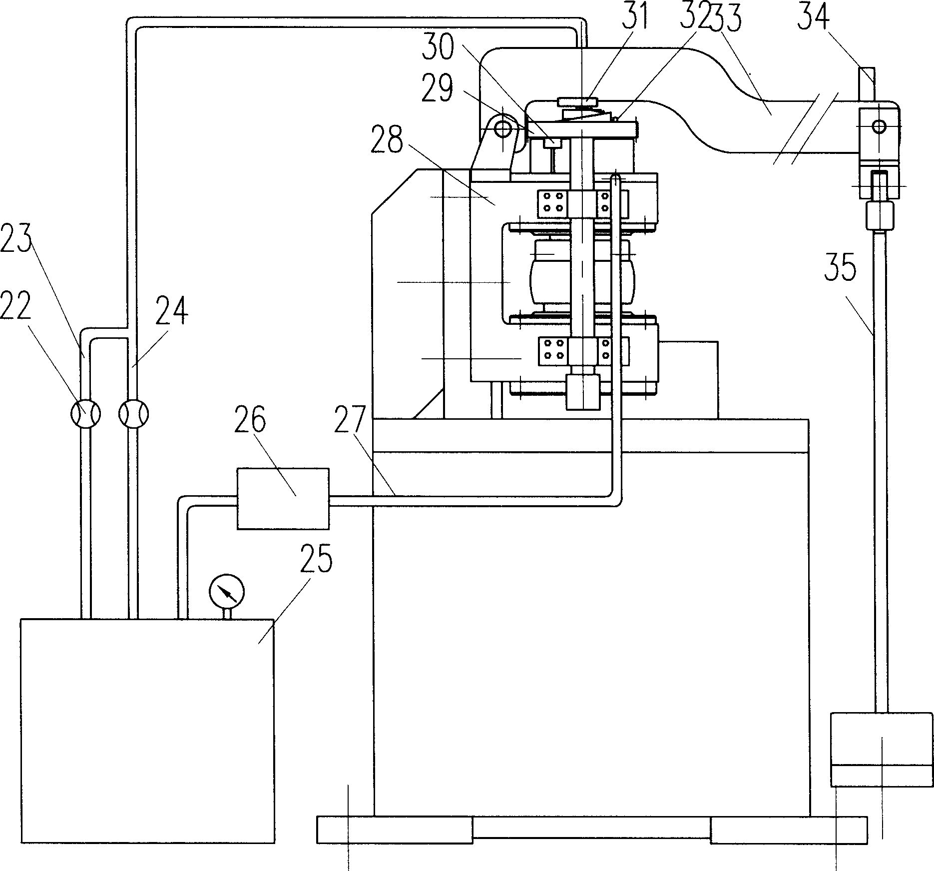
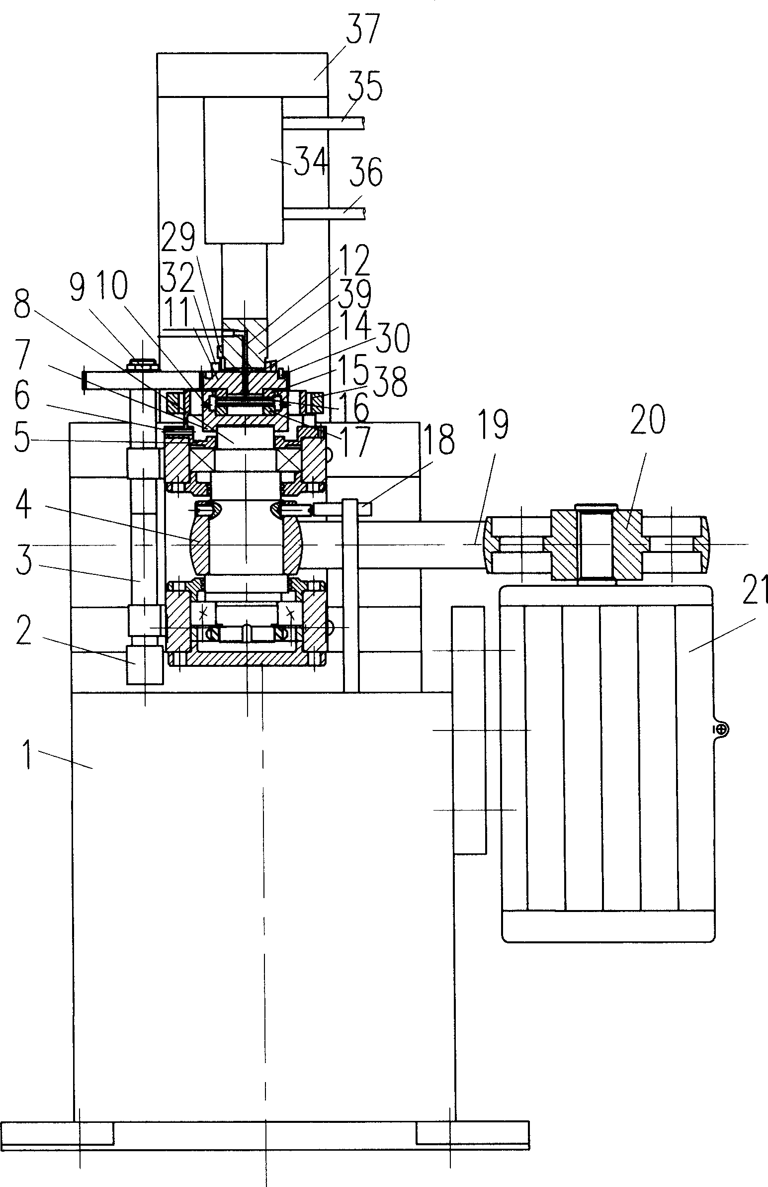

Image

  • Work condition analogue rolling contact fatigue tester
  • Work condition analogue rolling contact fatigue tester
  • Work condition analogue rolling contact fatigue tester

Examples


Embodiment 1

[0027] figure 1 , figure 2 It is an embodiment disclosed by the present invention (see figure 1 , figure 2 ), before the experiment, the surface of the upper test piece 15 and the lower test piece 17 to be detected is processed into a raceway or a plane according to the test requirements, and then the coating material is deposited on the upper test piece 15, the rolling body with the coating process equipment 16 or the surface of the lower test piece 17. Put the test piece into the test chamber 7, start the motor 21 to adjust the speed, then load, start the lubricating cooling device 25 and the signal acquisition device. The large pulley 20 of the variable frequency motor 21 drives the small pulley 4 and the transmission shaft 8 to rotate through the belt 19, and transmits the speed signal to the speed sensor 18, the transmission shaft 8 drives the test chamber 7 to rotate together, and the rolling body 16 and the lower test piece 17 follow of rotation. According to the...

Embodiment 2

[0029] image 3 It is another embodiment disclosed by the present invention (see image 3), the upper end of the hydraulic cylinder 36 is fixedly connected with the frame 39, the hydraulic pressure block 40 is installed on the piston rod of the hydraulic cylinder 36, and the acceleration sensor 34 is threaded on the arc plane of the emergency stop cam 11. Temperature sensor 32 is placed in the groove of emergency stop cam 11, and cylinder cam contacts with contact switch 31. The frequency conversion motor 21 drives the large pulley 20 to drive the small pulley 4 through the belt 19, the small pulley 4 drives the transmission shaft 8 to rotate, the transmission shaft 8 is fixed on the bracket 26 through the bearing and the bearing support, and the upper end of the transmission shaft 8 is connected to the test chamber 7 to drive the lower test piece 17 rotates, the upper end of the upper test piece 15 is the emergency stop cam 11, the teeth of the emergency stop cam 11 are mesh...


PUM


Abstract

The on-line work condition simulating rolling contact fatigue tester includes driving device, loading device, testing device and signal collecting device, and has temperature controlling cavity sleeved on the driving shaft, lower test cavity end interference fitted to the end of the driving shaft and set inside the temperature controlling cavity, test cavity with upper test sample, rolling part, lower test sample, abruptly stopping cam on the upper test sample, and rolling pin thrust bearing on the abruptly stopping cam and matching the pressure block below the loading lever. The present invention can simulate the contact fatigue, friction and wear process of friction pair with or without surface coating for relevant detection, and the instantaneous failure state may be kept by means of abrupt stopping unit.

Description

technical field [0001] The invention relates to a contact fatigue friction and wear testing machine, in particular to a contact fatigue friction and wear testing machine which simulates actual working conditions and can detect contact fatigue on-line. Background technique [0002] The surface friction and wear state and contact fatigue life are one of the main means to evaluate the quality of the coating process and the surface performance of the coating material. At present, there is no complete contact fatigue friction and wear testing machine that can simulate the actual working conditions to detect the friction and wear state and fatigue life of coating materials. [0003] Although the coating adhesion measuring instrument manufactured by Fangqun Company in the United States can measure the coating adhesion under standard microscopic conditions, the performance of the surface coating material obtained by local microscopic measurement is different from that of the surface...

Claims


Application Information

Patent Timeline
IPC IPC(8): G01N19/04G01N3/56G01N33/30G01M13/04
CPCG01N3/56G01N2203/0204G01N2203/0246
Inventor 杨育林
Owner YANSHAN UNIV
Learn More