Wavelength tunable surface plasmon resonance sensor

A surface plasmon and resonant sensor technology, which is applied in the direction of instruments, scientific instruments, measuring devices, etc., can solve the problems of method limitations, inability to provide tuned excitation or detection wavelengths, and damage the materials in the probe area, and achieve the effect of wide dynamic range

Inactive Publication Date: 2006-01-04
UNIV OF WASHINGTON
View PDF0 Cites 20 Cited by
  • Summary
  • Abstract
  • Description
  • Claims
  • Application Information

AI Technical Summary

Problems solved by technology

Also, removal and insertion of optical interference filters requires repeated alignment of the excitation and detection optical configurations
Furthermore, the method of ref is limited to optical configurations that provide discrete detection wavelength selection and does not provide the ability to tune excitation or detection wavelengths over a continuous range of values
Finally, the disclosed method exposes the sample to very intense light at wavelengths that cannot be detected with a CCD camera, which is detrimental to the formation of SPR images and may damage the material of the probe region.

Method used


Image

  • Wavelength tunable surface plasmon resonance sensor
  • Wavelength tunable surface plasmon resonance sensor
  • Wavelength tunable surface plasmon resonance sensor

Examples


example 1

[0096] Example 1: Characterization of an Exemplary SPR Sensor

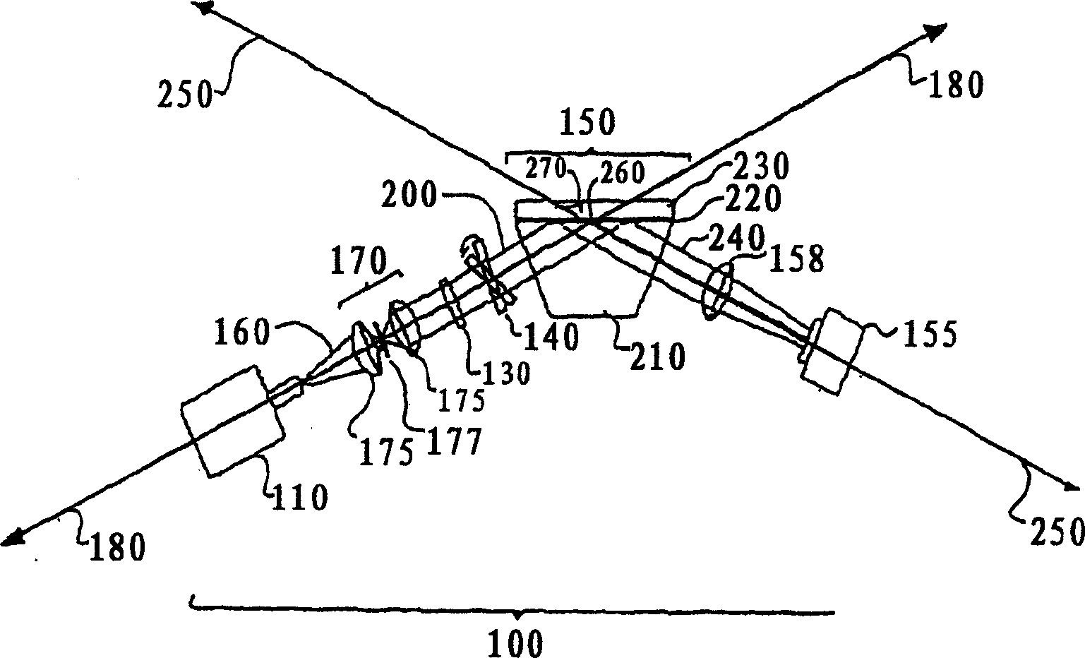
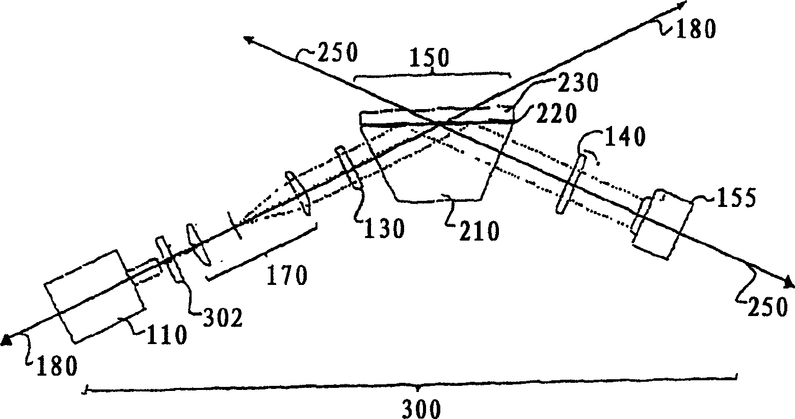
[0097] The ability of the SPR sensor of the present invention to sense changes in the refractive index of the probe region was demonstrated by experimental and computational studies. Specifically, it is an object of the present invention to provide SPR sensors capable of sensitive detection and characterization of changes in the refractive index of the probe region. Further, it is an object of the present invention to provide an SPR sensor with a large dynamic range capable of detecting materials with a wide range of refractive indices.

[0098] To achieve the aforementioned goals, the detection sensitivity and dynamic range of an exemplary SPR sensor were modeled in silico and estimated by monitoring the refractive index of a low-concentration sucrose solution. Exemplary SPR sensors employed in these studies are based on the Kretschmann configuration and as Figure 5 shown. The polychromatic light source was...

example 2

[0105] Example 2: SPR images of thiol maps and bovine serum albumin on a gold surface

[0106] To estimate the sensitivity and spatial resolution of the inventive SPR imaging device, SPR images of the thiol map were generated by an exemplary SPR sensor. Thiol maps on gold surfaces (comprising ~1 nm of Cr and ~45 nm of gold e-beam deposited from Fisher Scientific onto standard microscope slides) were prepared using the polydimethylsiloxane (PDMS) stamping protocol . The employed protocol was optimized to minimize transfer of material from the PDMS imprint to the surface and to produce a monolayer of thiols on the surface. All images were acquired with p-polarized light. Figure 12 shows a series of images of thiol and water maps acquired with optical interference filters at various tilt angles. Figure 12A corresponds to a central wavelength of 857 nm, Figure 12B corresponds to a central wavelength of 852 nm, Figure 12C corresponds to a central wavelength of 845 nm, Figure 1...


PUM

PropertyMeasurementUnit
thicknessaaaaaaaaaa
reflectanceaaaaaaaaaa

Abstract

This invention provides methods, devices and device components for sensing, imaging and characterizing changes in the composition of a probe region. More particularly, the present invention provides methods and devices for detecting changes in the refractive index of a probe region positioned adjacent to a sensing surface, preferably a sensing surface comprising a thin conducting film supporting surface plasmon formation. In addition, the present invention provides methods and device for generating surface plasmons in a probe region and characterizing the composition of the probe region by generating one or more surface plasmon resonances curves and / or surface plasmon resonance images of the probe region.

Description

[0001] Statement Regarding Federal Funding for Research or Development [0002] This work was funded by a US government grant, NIDCR license 1UO1 DE14971-01. Background technique [0003] Surface plasmon resonance (SPR) microscopy is a technique for probing chemical and physical changes in a probed region adjacent to a sensing surface by exciting surface plasmons (SPs). A variety of sensors based on SPR technology have been developed, providing a sensitive device for characterizing the thickness and refractive index of ultrathin films present on the surface of metallic thin films. In recent years, SP sensors have been widely used to characterize the chemical and physical properties of various biomaterials and to detect binding events in real time. For example, SP sensors have been successfully used to characterize the morphology of a large number of surfaces, probe kinetics and dynamics between proteins, between proteins and DNA, and between proteins and small molecules, moni...

Claims


Application Information

Patent Timeline
Patent Type & Authority Applications(China)
IPC IPC(8): G01N21/55
CPCG01N21/648G01N21/553
Inventor 保罗·雅格伊莱恩·S.·付
Owner UNIV OF WASHINGTON
Why Eureka
Try Eureka