High energy ball mill method with plasma aid

A plasma and high-energy ball milling technology, applied in grain processing and other directions, can solve the problems of low powder input mechanical energy, long processing time, serious powder agglomeration, etc. short-term effect

Active Publication Date: 2006-01-11
SOUTH CHINA UNIV OF TECH
View PDF0 Cites 61 Cited by
  • Summary
  • Abstract
  • Description
  • Claims
  • Application Information

AI Technical Summary

Problems solved by technology

But its disadvantages are: affected by the vibration amplitude of the ball mill tank, the mechanical energy input to the powder is not very high, the particle size of the product powder is basically at the micron level, and the powder agglomerates seriously, the particle size distribution is wide, and it is difficult to obtain a powder with a particle size at the nanometer level; The processing efficiency is low, and when it is applied to mechanical alloying, the processing takes a long time

Method used


Image

  • High energy ball mill method with plasma aid
  • High energy ball mill method with plasma aid
  • High energy ball mill method with plasma aid

Examples


Embodiment 1

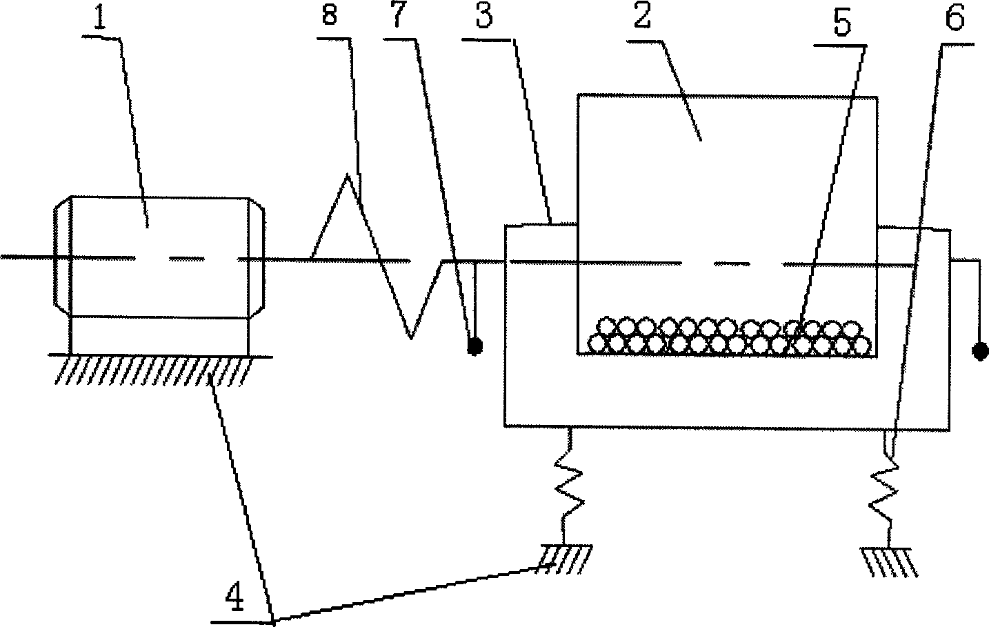
[0029] Such as figure 1 As shown, realize the plasma-assisted high-energy ball milling device of the present invention, comprise driving motor 1, ball mill jar 2, frame 3, base 4, ball mill jar 2 is installed on frame 3, and grinding ball 5 is placed inside it, frame 3 is installed on the base 4 through the spring 6, and an exciting block 7 is arranged on the outside thereof. The driving motor 1 is installed on the base 4, and is connected with the frame 3 and the exciting block 7 through the elastic coupling 8 respectively.

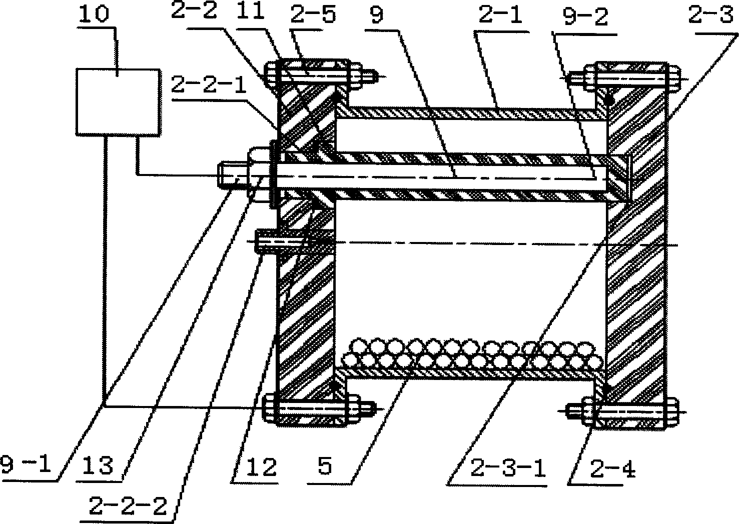
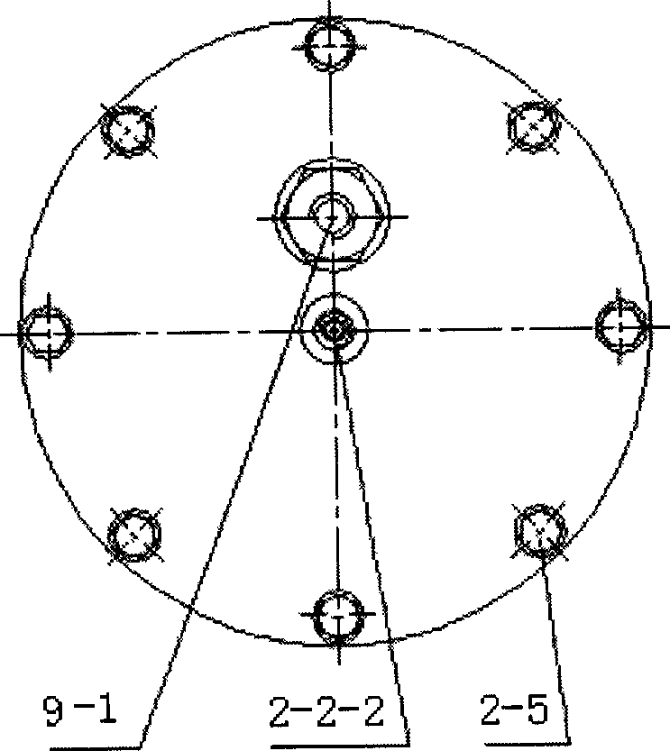
[0030] Such as figure 2 , 3 As shown, the grinding ball 5 is placed in the ball milling pot 2, and the ball milling pot 2 is also connected with an electrode rod 9 and a plasma power supply 10. The ball milling pot 2 includes a cylinder body 2-1, a front cover plate 2-1, and a rear cover plate 2- 3. The flanges at both ends of the cylinder 2-1 are sealed and connected to the front cover 2-2 and the rear cover 2-3 respectively through the sealing ring ...

Embodiment 2

[0040] Using the device of Example 1, the process conditions of this plasma-assisted high-energy ball milling method are basically the same as those of Implementation 1, except that the total volume of balls accounts for 75% of the volume of the ball milling tank, and balls with a diameter of 22 mm account for 75% of the total ball milling volume. 15%, grinding balls with a diameter of 18mm accounted for 75% of the total number of grinding balls, grinding balls with a diameter of 10mm accounted for 10% of the total number of grinding balls, and the loose volume of the powder to be processed accounted for 130% of the gap between the grinding balls; the negative pressure of the ball mill tank to 0.01Pa; the discharge voltage is 3kv, the frequency is 5kHz to realize corona discharge; the excitation block adopts 10mm double amplitude, and the motor speed is 930r / min.

Embodiment 3

[0042] Using the device of Example 1, the process conditions of this plasma-assisted high-energy ball milling method are basically the same as those of Implementation 1, except that the total volume of balls accounts for 72% of the volume of the ball milling tank, and balls with a diameter of 20 mm account for 72% of the total ball milling volume. 12%, grinding balls with a diameter of 18mm accounted for 78% of the total number of grinding balls, grinding balls with a diameter of 10mm accounted for 10% of the total number of grinding balls, and the loose volume of the powder to be processed accounted for 80% of the gap between the grinding balls; the negative pressure of the ball mill tank to 0.05Pa; the discharge voltage is 10kv, the frequency is 20kHz, and corona discharge is realized; the excitation block adopts 8mm double amplitude, and the motor speed is 930r / min.


PUM


Abstract

A plasma aided high-energy ball grinding method includes such steps as installing the front cover plate and rod electrode of ball grinder, respectively connecting the ball grinder and rod electrode to the poles of plasma power supply, loading the powder to be ground in the ball grinder, pumping negative pressure, filling discharging gas medium, turning on the plasma power supply, regulating discharge parameters for corona discharge or glow discharge, and turning on the motor to drive the vibration exciting block for ball grinding.

Description

technical field [0001] The invention relates to nano-micron powder preparation and mechanical alloying methods, and in particular provides a plasma-assisted high-energy ball milling method. Background technique [0002] The method of preparing alloy powder by high-energy ball milling is one of the most commonly used technologies for nano-micron material preparation and mechanical alloying. It usually uses high-energy ball mill rotation or vibration to refine metal or alloy powder to nano-micron scale, that is: two Or two or more powders are put into the ball milling tank of the high-energy ball mill at the same time for high-energy ball milling. The powder particles are calendered, pressed, crushed, and pressed repeatedly (that is, cold welding-crushing-cold welding). The powder grain and particle size are continuously refined, and finally nano-micron ultrafine alloy powder with uniform distribution of structure and composition can be obtained. Bec...

Claims


Application Information

Patent Timeline
Patent Type & Authority Applications(China)
IPC IPC(8): B02C17/14B02C19/18
Inventor 朱敏戴乐阳曹彪曾美琴欧阳柳章童燕青
Owner SOUTH CHINA UNIV OF TECH
Why Eureka
Try Eureka