Power road electric closer car

A technology for electric cars and roads, which is applied in the field of vehicles in the transportation field. It can solve the problems of poor aerodynamic performance, roads need to be rebuilt, and can only drive in one direction, so as to save energy and resources, improve battery life, and reduce construction costs. cost effect

Inactive Publication Date: 2006-01-11
SHANGHAI JIAO TONG UNIV
View PDF1 Cites 43 Cited by
  • Summary
  • Abstract
  • Description
  • Claims
  • Application Information

AI Technical Summary

Problems solved by technology

Its shortcomings are: (1) the road needs to be rebuilt; (2) the special road is single-lane and can only travel in one direction; (3) the vehicle is fixed horizo

Method used


Image

  • Power road electric closer car
  • Power road electric closer car
  • Power road electric closer car

Examples


Embodiment Construction

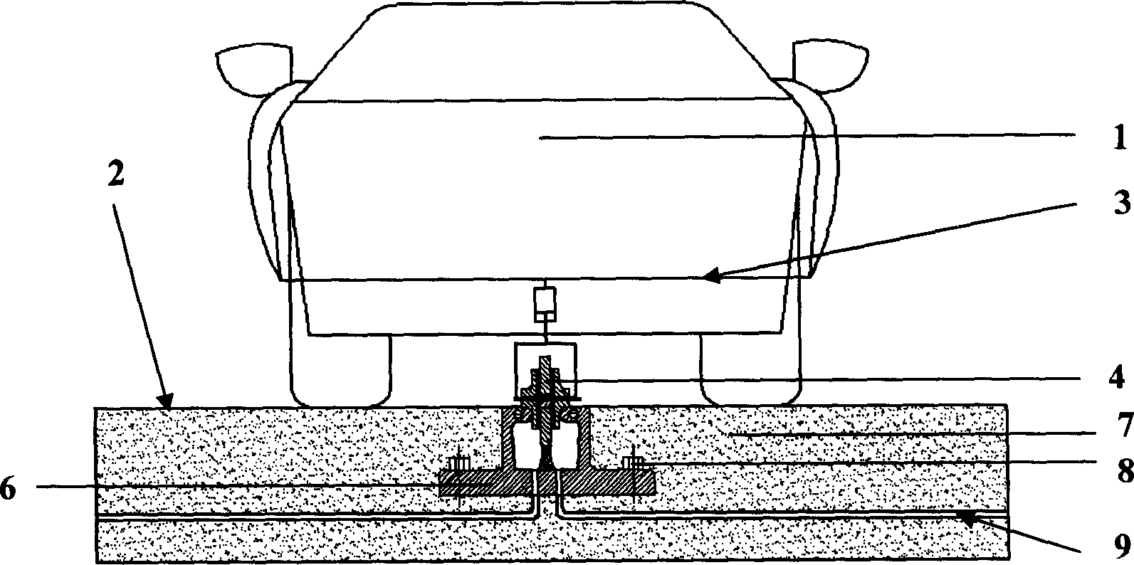
[0028] Such as figure 1 Shown, the present invention comprises two parts: electric car 1 and power road 2.

[0029] The electric car 1 includes: a chassis 3, a power receiving wheel mechanism 4, and an automatic driving system 5. The power receiving wheel mechanism 4 is arranged in the chassis 3, and the automatic driving system 5 controls the car to drive automatically on the track. The power road 2 includes: concave power supply rail 6, subgrade 7, fixing bolts 8, sewage pipe 9, concave power supply rail 6 is laid on the elevated or expressway according to the lane, the upper surface is flat with the road surface and the width of the groove is smaller than that of the tire Width, concave power supply rail 6 is fixed by fixing bolt 8, and sewage pipe 9 is buried in roadbed 7 li.

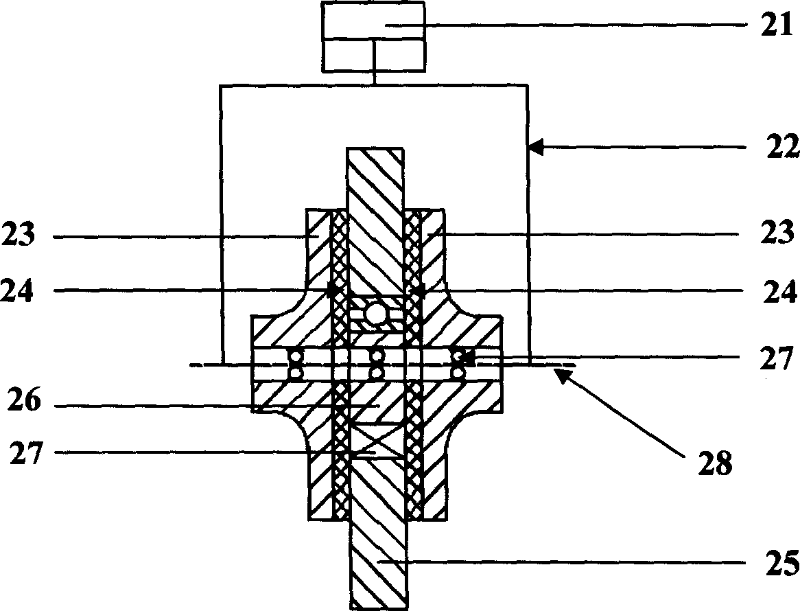
[0030] Such as figure 2 As shown, the power receiving wheel mechanism 4 includes: an oil cylinder 21, a wheel frame 22, two outer wheels 23, two insulating wheels 24, an intermediate wheel 25, an e...


PUM


Abstract

A combination of electric car and power road features that each electric car has a chassis, an electric receiving wheel unit arranged in the chassis and an automatic drive system, and said power road is characterized by that each lane on the road has a concave electric power supplying rail matched with said electric receiving wheel unit of each car.

Description

technical field [0001] The invention relates to a vehicle in the traffic field, in particular to a powered road electric car. Background technique [0002] Electric vehicles can be divided into three categories according to their power sources: on-board power, external power supply, and the combination of on-board power and external power supply. Vehicle-powered electric vehicles include: battery electric vehicles, hybrid electric vehicles, and fuel cell electric vehicles. Battery electric vehicles store electrical energy in secondary batteries through chargers; hybrid electric vehicles are equipped with electric drive systems and auxiliary power units (APUs), where APUs are prime movers that burn certain fuels (or fuel cells) or powered by Generator set driven by prime mover. Due to the low specific energy and specific power of the battery, the mileage of battery electric vehicles is short, and the acceleration and climbing performance are weak; hybrid electric vehicles s...

Claims


Application Information

Patent Timeline
IPC IPC(8): B60F1/00B60L5/38B60M1/30
Inventor 王成焘李玉德
Owner SHANGHAI JIAO TONG UNIV
Why Eureka
Try Eureka