
Automatic continuous copper foil annealing system

A copper foil and annealing technology, which is applied in furnaces, heat treatment equipment, heat treatment furnaces, etc., can solve the problems that the physical properties of copper foil cannot meet the requirements, and achieve the effect of bright surface, simple structure and neat edges

Inactive Publication Date: 2006-01-11
朱元康
View PDF0 Cites 1 Cited by
  • Summary
  • Abstract
  • Description
  • Claims
  • Application Information

AI Technical Summary

Problems solved by technology

This set of equipment is a mature process equipment for copper strip annealing. However, during the copper foil annealing process, since the thickness of the copper foil is only between 0.01mm and 0.03mm, when the product is released from the furnace, it is often found that the copper foil on the edge of the furnace is sintered. Phenomenon, and the physical properties of the copper foil in the middle part can not meet the requirements

Method used


Image

  • Automatic continuous copper foil annealing system
  • Automatic continuous copper foil annealing system
  • Automatic continuous copper foil annealing system

Examples


Embodiment Construction

[0014] Below the present invention will be described further in conjunction with the embodiment in the accompanying drawing:

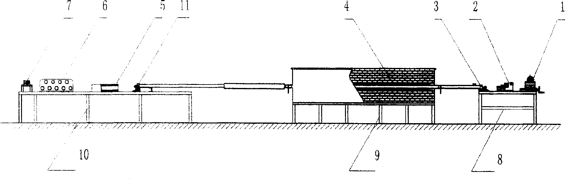
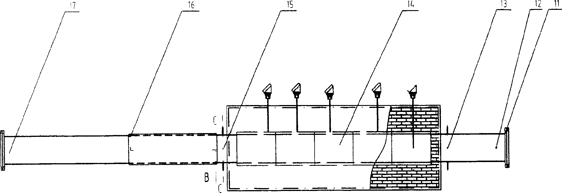
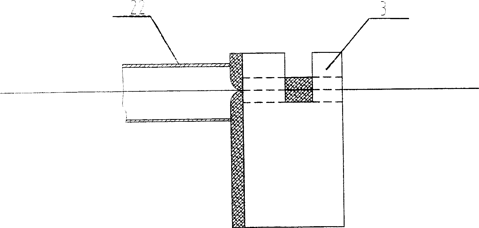
[0015] The present invention mainly consists of a discharge rack 1, a discharge shaft 2, seals 3, 11, a horizontal continuous annealing furnace 4, a dryer 5, a guide roller shaping device 6, a winding device 7, workbenches 8, 10, and a work frame 9 , copper foil inlet 12, first inlet 13 of mixed gas, furnace heating zone 14, air intake zone 15, water jacket cooling zone 16, natural cooling zone 17, thermocouple 18, light refractory material 19, furnace It is composed of a tank shell 20, a furnace tube 21, a furnace tank 22, left and right side plates 23, 27, tracks 24, mounting holes 25, guide rollers 26, magnetic powder couplers 28, and the like.

[0016] The present invention mainly uses the discharging rack 1, the discharging shaft 2, and the seal 3 at one end of the annealing furnace to be placed on the workbench 8 in sequence, the main body of the...


PUM


Abstract

A continuous automatic annealing system for annealing and shaping the copper foil band features that the main body of a horizontal continuous annealing furnace is arranged on a supporting frame, the payoff unit, payoff reel and one enclosed end of said annealing furnace are arranged on a bench, and the another enclosed end of said annealing furnace, drier, guiding-shaping unit and take-up unit are arranged on another bench.

Description

technical field [0001] The invention relates to an automatic continuous copper foil bright annealing system, in particular it is used for annealing and shaping non-ferrous metal strips and foils, and belongs to the technical field of heat treatment equipment. Background technique [0002] Before the present invention was made, in the prior art, a vertical vacuum annealing furnace was usually used for foil annealing, and the vertical vacuum annealing furnace was composed of a vertical vacuum annealing furnace body, a heating wire, a vertical vacuum furnace, Vacuum furnace cover, thermocouple, gate valve, vacuum pressure gauge, etc. The furnace body of the annealing furnace is equipped with a vacuum furnace furnace, and the heating wire is wound around the inner circle of the vacuum furnace body. The thermocouple, gate valve and vacuum pressure gauge are connected to the vacuum furnace furnace through the vacuum furnace cover. This set of equipment is a mature process equipme...

Claims


Application Information

Patent Timeline
IPC IPC(8): C21D9/56C21D1/26
Inventor 朱元康
Owner 朱元康
Learn More