Welding disk vision identifying and positioning system for flexible laser ball implanting machine

A visual identification and positioning system technology, applied in laser welding equipment, welding equipment, electrical components, etc., can solve the problem that cannot meet the development trend of BGA chip miniaturization, high-density I/O number, pad positioning accuracy and repeated positioning Low precision ball planting efficiency, inconvenient popularization, promotion and commercialization, etc., to achieve the effect of reducing precision requirements and the number of sensors, large commercial value, and increasing flexibility

Inactive Publication Date: 2006-01-11
SHANGHAI JIAO TONG UNIV
View PDF0 Cites 34 Cited by
  • Summary
  • Abstract
  • Description
  • Claims
  • Application Information

AI Technical Summary

Problems solved by technology

Although this type of ball planting equipment can complete the function of solder ball implantation during rework, because it completely relies on manual identification and positioning of the pads, the labor intensity of the ball planting work is high, and the positioning accuracy and repeatabili

Method used


Image

  • Welding disk vision identifying and positioning system for flexible laser ball implanting machine

Examples


Embodiment Construction

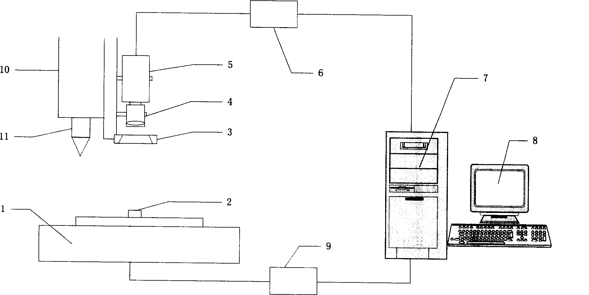
[0008] The technical solution of the present invention will be further described below in conjunction with the accompanying drawings.

[0009] The system structure of the present invention is as figure 1 As shown, on the fixed bracket 10 of the ball planting head 11 installed, a CCD camera 5 is installed, the lens 4 is connected with the CCD camera 5 through the C interface, and the lens 4 is fastened on the fixed bracket 10 simultaneously to prevent loosening. When the CCD camera 5 and the lens 4 are fixedly connected to the fixed bracket 10, the central axis and the central axis of the ball planting head 11 should be parallel to each other, and should be as close as possible to each other without interfering with each other. Then, a ring-shaped LED light source 3 is installed directly below the lens 4, the purpose is to avoid the impact of ambient light changes on the later image processing and system positioning accuracy. The type and size of the ring-shaped LED light sour...


PUM


Abstract

This invention relates to a bonding pad visual identifying and a positioning system of a soft laser ball-implantation machine, which installs a CCD camera on a fixed frame with an implanted ball head, the axel wire of the camera and the lens is parallel to the axle wire of the implanted ball head and get close to each other as much as possible under the condition not interfering each other, a ring LED light source is installed just under the lens to avoid the influence to late image process and system position accuracy after the surrounding light rays change, the camera is connected with an image collecting card in the PC set, the x-y shaft movement platform under the ball head is connected with the PC set via the movement controller, which can position the bonding pad and implant solder ball automatically or semi-automatically, send the image signals shot by the camera to the PC for memory after digitalized by the image collection card and the image process software processes and analyzes it to find out the center of the bonding pad, then the controller controls the x-y shaft motion platform to let the pad just under the ball head to finish the implantation.

Description

technical field [0001] The invention relates to a pad visual recognition and positioning system of a flexible laser ball planting machine, which can be used for precise positioning in semiconductor packaging equipment, and belongs to the fields of visual recognition and positioning, advanced electronic manufacturing and mechatronics. Background technique [0002] Ball grid array (BGA) packaging technology is the latest cutting-edge electronic packaging technology that has been widely used in the electronic packaging industry in the past two years. With the BGA packaging form, the ball planting technology has become the main bottleneck of domestic BGA package ICs. With the great development of BGA packaging, it is expected that ICs using BGA packaging will become the mainstream of integrated circuits in my country in recent years. The key operation of ball planting technology is to accurately position the pads on the BGA chip. The movement accuracy of the motion platform du...

Claims


Application Information

Patent Timeline
IPC IPC(8): H01L21/60B23K26/00H05K3/34
CPCH01L2924/14H01L24/78H01L2224/78301H01L2924/01006H01L2924/00014H01L2224/78H01L2224/48H01L2924/00012
Inventor 丁汉朱利民熊振华罗红根
Owner SHANGHAI JIAO TONG UNIV
Why Eureka
Try Eureka