
Low interference frequency change power for high-voltage testing
A high-voltage test and variable frequency power supply technology, which is applied to electrical components, conversion equipment for intermediate conversion to DC, conversion of AC power input to DC power output, etc., can solve problems such as partial discharge test, large interference, and difficulty in field wiring , to achieve the effect of simple and convenient operation, ensuring safety and reducing demand
- Summary
- Abstract
- Description
- Claims
- Application Information
AI Technical Summary
Problems solved by technology
Method used
Image

Examples
Embodiment Construction
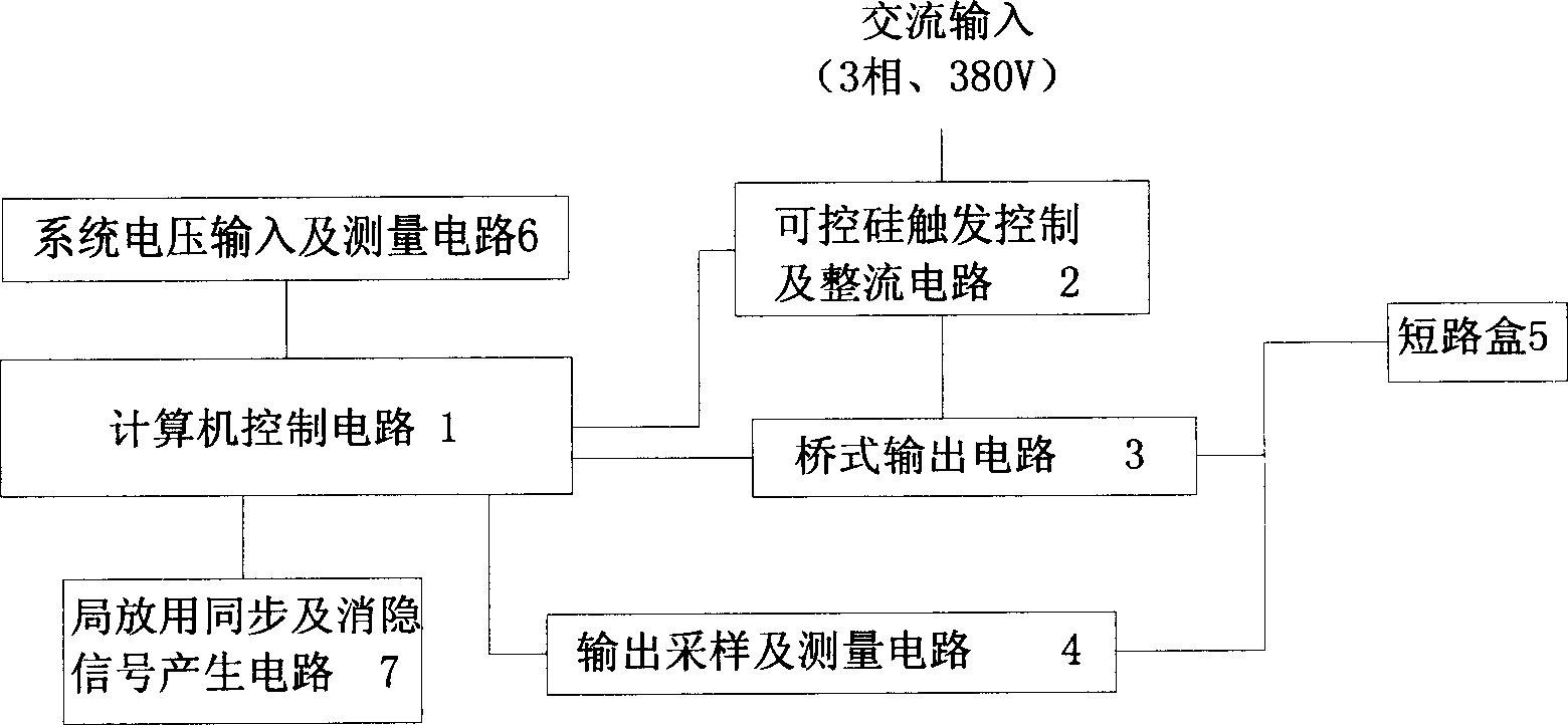
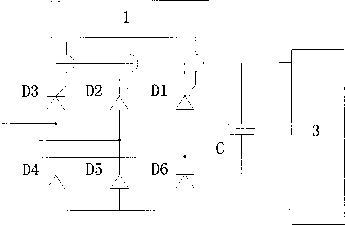
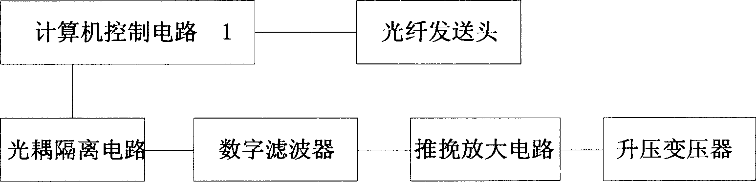
[0016] like figure 1 As shown, the present invention includes: a computer control circuit 1, a thyristor trigger control and rectification circuit 2, a bridge output circuit 3, an output sampling and measurement circuit 4, a short-circuit box 5, a system voltage input and measurement circuit 6, a partial discharge circuit Synchronization and blanking signal generation circuit 7 . The three-phase AC input is sent to the thyristor trigger control and rectifier circuit 2; the control signal of the thyristor trigger control and rectifier circuit 3 is generated by the computer control circuit 1, and its rectified output is sent to the bridge output circuit 3; the bridge output circuit The output signal of 3 is sent to the short-circuit box 5 and sent to the output sampling and measurement circuit 4, and the output sampling and measurement circuit 4 sends the sampled signal to the computer control circuit 1 after passing through the measurement circuit; similarly, the voltage of the...
PUM
 Abstract
Description
Claims
Application Information