Multi-layer capacitive coupling in phased array antennas

A phased array antenna, dipole antenna technology, applied in the middle position between the end points of the antenna to feed, the device for manufacturing the antenna array, the direction of the antenna, etc.

Inactive Publication Date: 2006-01-11
HARRIS CORP
View PDF3 Cites 15 Cited by
  • Summary
  • Abstract
  • Description
  • Claims
  • Application Information

AI Technical Summary

Problems solved by technology

However, when this antenna is used as a feed-through lens antenna, the above-mentioned limitations arise accordingly

Method used


Image

  • Multi-layer capacitive coupling in phased array antennas
  • Multi-layer capacitive coupling in phased array antennas
  • Multi-layer capacitive coupling in phased array antennas

Examples


Embodiment Construction

[0024] The present invention will now be described more fully with reference to the accompanying drawings, which illustrate preferred embodiments of the invention. However, the present invention may be implemented in many different ways and should not be considered limited to the embodiments described herein. Rather, these embodiments are provided so that this disclosure will be thorough and complete, and will fully convey the scope of the invention to those skilled in the art. Like reference numbers refer to like parts throughout the drawings, and, in alternate embodiments, apostrophes and double apostrophes are used to refer to like parts.

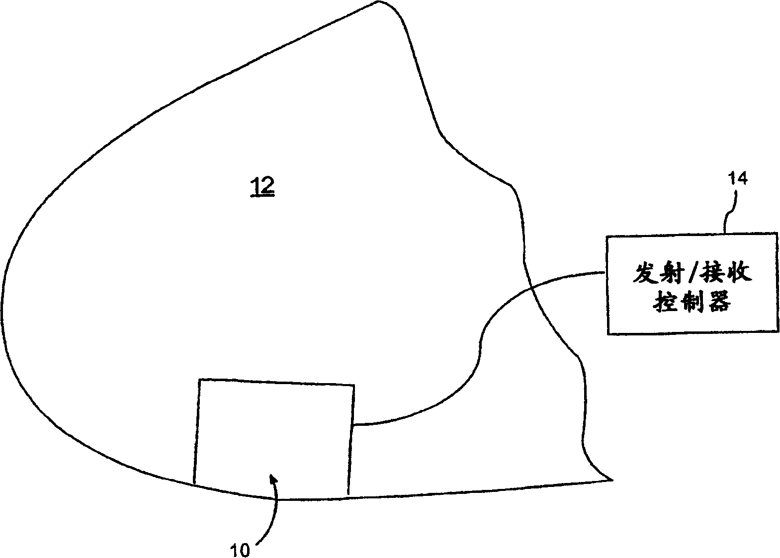
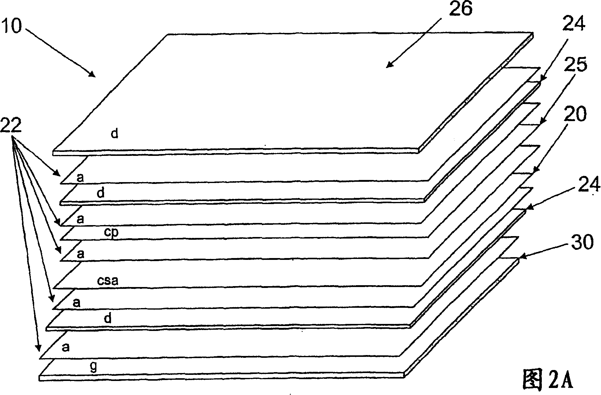
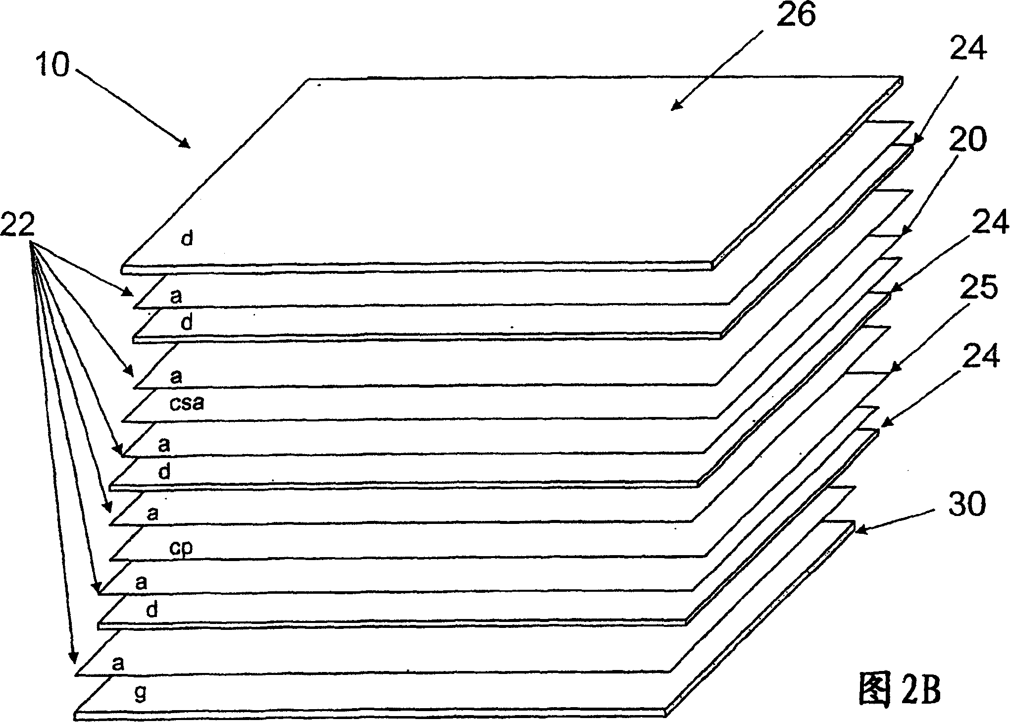
[0025] First, refer to figure 1 and 2(A-C), which illustrate the broadband phased array antenna 10 according to the present invention. For example, the antenna 10 may be mounted on the nose 12 of an aircraft or spacecraft, or may be mounted on other rigidly mounted components having a planar or non-planar three-dimensional shape, and t...


PUM


Abstract

A phased array antenna(10) includes a current sheet array (20) on a substrate (23), at least one dielectric layer (24) between the current sheet array and a ground plane (30), and at least one conductive plane (25) adjacent to the substrate for providing additional coupling between adjacent dipole antenna elements of the current sheet array.

Description

technical field [0001] The construction of the present invention relates generally to the field of communications, and more particularly, the present invention relates to phased array antennas. Background technique [0002] Existing microwave antennas include a wide variety of configurations for various applications such as satellite reception, long-range broadcast, or military communications. Typically, printed circuit antennas are utilized to achieve the required characteristics of low cost, light weight, small form factor and mass production. The simplest form of a printed circuit antenna is a microstrip antenna, where a flat conductive part is separated from a substantially continuous ground part using a dielectric sheet of uniform thickness. One example of a microstrip antenna is disclosed in US Patent No. 3,995,277 to Olyphant. [0003] The antenna is designed in an array and can be used in communication systems such as identification friend / foe (IFF) systems, person...

Claims


Application Information

Patent Timeline
Patent Type & Authority Applications(China)
IPC IPC(8): H01Q9/28H01Q3/46H01Q21/00H01Q21/06
CPCH01Q3/46H01Q21/0087H01Q21/062H01Q9/285H01Q1/405
Inventor 蒂莫西·E.·德拉姆斯蒂芬·B.·布朗安东尼·M.·琼斯兰迪·布泽肖恩·奥尔蒂兹
Owner HARRIS CORP
Why Eureka
Try Eureka