
Capacity variable rotary internal combustion engine

A rotary engine and variable volume technology is applied in the field of power machines to achieve the effects of eliminating vibration and noise, reducing manufacturing costs and simplifying structure

Inactive Publication Date: 2006-01-18
葛开茂
View PDF0 Cites 3 Cited by
  • Summary
  • Abstract
  • Description
  • Claims
  • Application Information

AI Technical Summary

Problems solved by technology

But the reason why it has not been widely used and appeared in front of us is that it still has some shortcomings.

Method used

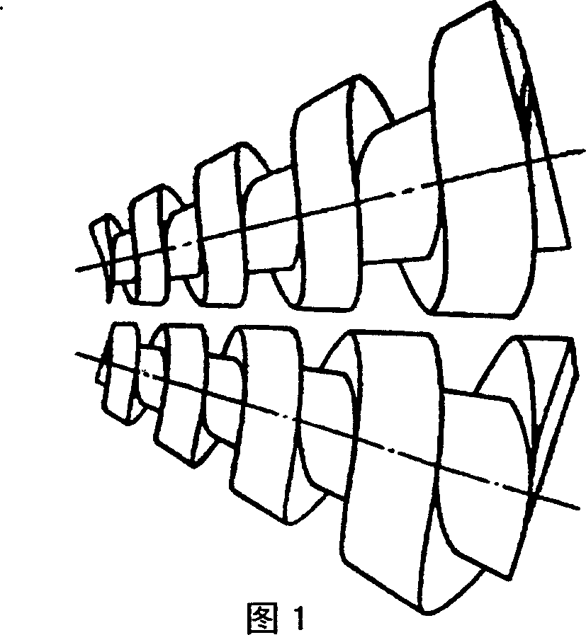
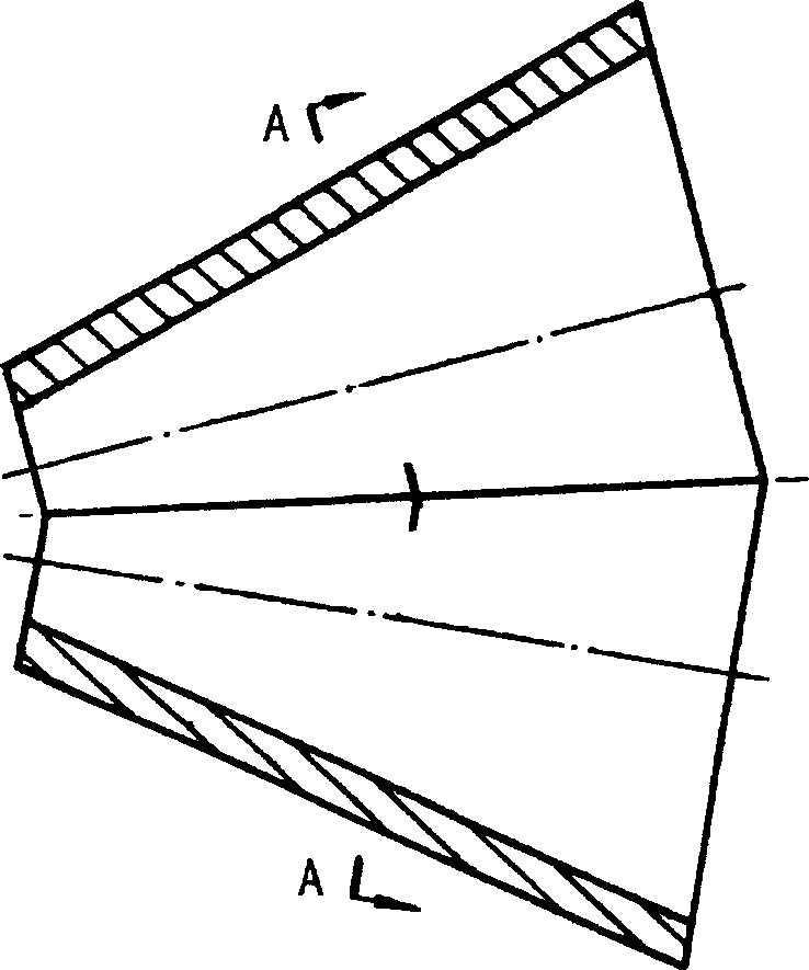
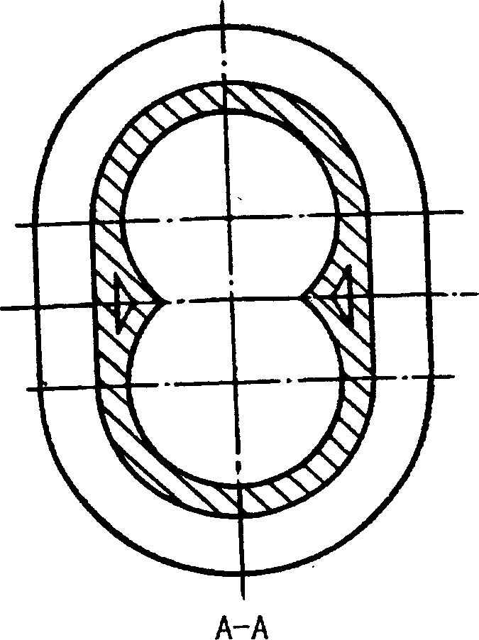

Image

  • Capacity variable rotary internal combustion engine
  • Capacity variable rotary internal combustion engine
  • Capacity variable rotary internal combustion engine

Examples


Embodiment Construction

[0037]The variable volume rotary engine of the present invention is a brand-new engine, and there are many technical categories involved in it. Including engine design and manufacturing and electrical control, basic materials and machinery manufacturing, etc. It needs the cooperation of many people to implement it. There are two specific implementation methods: one is to conduct trial production through relevant engine research institutes, and enter the factory for production after finalization. The other is to conduct trial production through a joint factory or company and university, and then transfer to production after finalizing the shape.


PUM


Abstract

This invention relates to a volume variable rotor generator, which is located with crank bar like piston generator and drainage gate. The generator is to use the rotor with increasing screw distance in cylinder for gear to form the volume cylinder to provide the conversion from heat energy to mechanic energy. The rotors output dynamic force as rotor and the generator compressed air uses the rotor or other same compressor.

Description

Technical field: [0001] The invention relates to a power machine capable of converting heat energy into mechanical energy, which is a rotary engine. Background technique: [0002] Currently, gasoline engines and diesel engines are commonly used as power engines, and they are widely used in transportation and industrial and agricultural production as power sources. But these two kinds of engines all have piston and connecting rod in structure, and their reciprocating motion and exhaust valve are impacted by the exhaust gas pressure that opens suddenly, cause them to appear inevitable vibration and send out very loud noise in the work. The vibration and noise of the engine destroy our peaceful living and working environment. Better engine performance has been desired, and great efforts have been made, with some success in localized performance improvements. But the crank-link mechanism that has been used for many years has been preserved to this day. People are looking forw...

Claims


Application Information

Patent Timeline
IPC IPC(8): F01C1/16F01C1/08F02B53/02F02B3/00
CPCY02T10/17Y02T10/12
Inventor 葛开茂
Owner 葛开茂
Learn More