
CWDM light filter

A technology of optical filter and film layer, which is applied in the field of optical filter and can solve problems such as light leakage or noise

Inactive Publication Date: 2006-01-18
东莞信泰光学有限公司
View PDF2 Cites 17 Cited by
  • Summary
  • Abstract
  • Description
  • Claims
  • Application Information

AI Technical Summary

Problems solved by technology

[0011] Most of the general optical communication CWDM filters are formed by stacking several multi-layer films with the same structure at quarter wavelength, but in the 1260nm-1640nm band, except for the signal of this filter, other wavelength ranges will be light leakage or noise

Method used


Image

  • CWDM light filter
  • CWDM light filter
  • CWDM light filter

Examples


Embodiment Construction

[0025] Now, the CWDM (coarse wavelength division multiplex) filter of the present invention will be further described in detail in conjunction with the accompanying drawings.

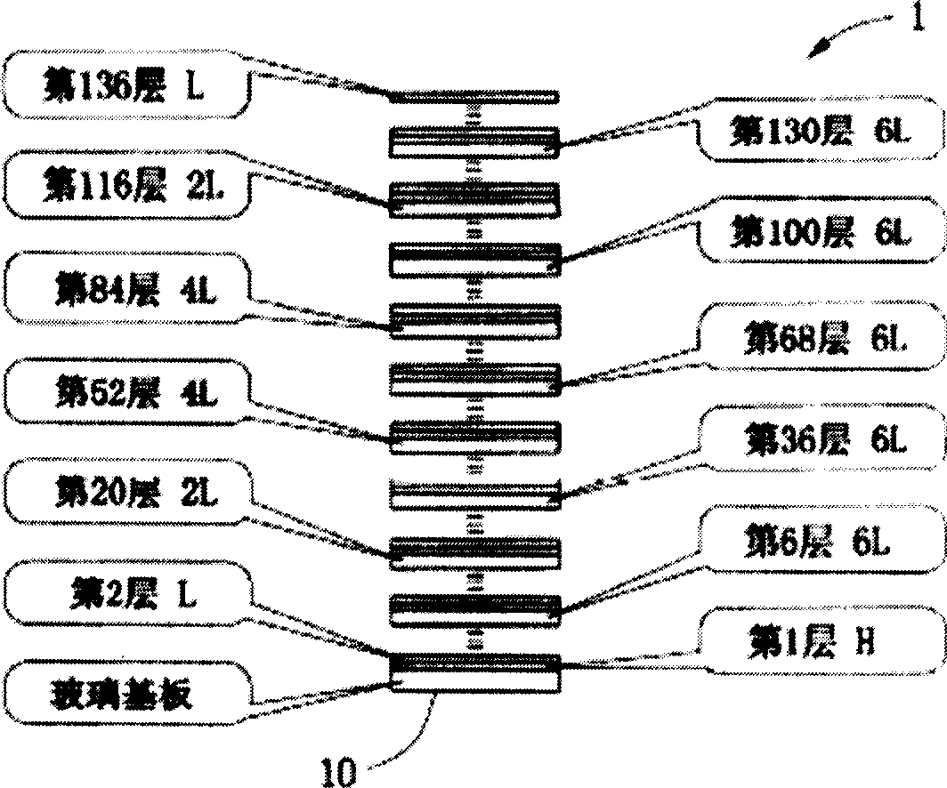
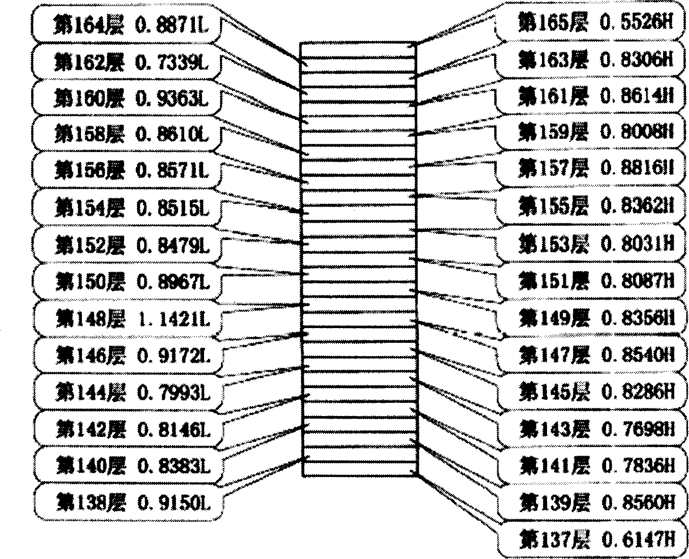
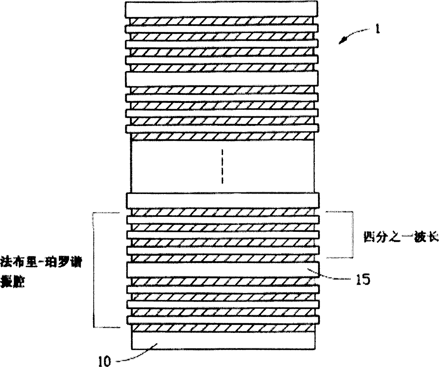
[0026] like figure 1 , 2 As shown in and 3, the present invention relates to a CWDM optical filter 1, including a first part and a second part. Among them, the first part includes at least two Fabry-Perot cavity structures; the second part includes repeated stacking of high and low refractive index film layers on the first part; The layer structure of the wavelength.

[0027]The number of alternately stacked high and low refractive index film layers in the second part can be 28 layers, 40 layers, 50 layers, or 60 layers, etc. The specific number of layers can be determined according to specific requirements and application environment, and the present invention takes 40 layers as the preferred number of film layers for implementation.

[0028] The at least two Fabry-Perot resonator structures of the...


PUM

PropertyMeasurementUnit
wavelengthaaaaaaaaaa

Abstract

The invention relates to a CWDM filter glass which comprises first part and second part, wherein first part comprises at least two Fabry-Perot cavity resonator structures; second part comprises foil structure which is formed by coupled high, low refractivity foil layer non-quarter ware of first part. The at least two Fabry-Perot cavity resonator structures of first part is a generally adopted structure. The foil thickness of non-quarter ware is casual generated by computer with the center ware at 1470 nm according to the given ware range.

Description

technical field [0001] The present invention relates to an optical filter, in particular to a CWDM optical filter suitable for a coarse wavelength division multiplexing system (CWDM; coarse wavelength division multiplex). Background technique [0002] Optical filter, or optical filter (optical filter) is a wavelength selective device, which has important applications in optical fiber communication systems and optical sensor systems. Optical filters are divided into two types: passive and active. Passive optical filters are based on prisms, diffraction gratings, and spectral (frequency) filters; active optical filters are passive devices and tunable detectors. Combined, each detector is tuned to a specific frequency. [0003] Among the passive optical filters, there is an interference film filter, which uses high and low refractive index materials to be deposited on substrates made of glass and other materials with a pre-designed thickness (usually λ / 4) to meet the requireme...

Claims


Application Information

Patent Timeline
Patent Type & Authority Applications(China)
IPC IPC(8): G02B5/20H04J14/00B32B17/06
Inventor 张陈益升
Owner 东莞信泰光学有限公司
Learn More