Method of optimal system reconfiguration after intelligent antenna array element failure

A smart antenna and optimal configuration technology, which is applied in the field of mobile communication, can solve the problems of signal processing method performance degradation, etc., and achieve the effect of optimal performance and maintaining communication functions

Inactive Publication Date: 2006-01-18
ZTE CORP
View PDF0 Cites 13 Cited by
  • Summary
  • Abstract
  • Description
  • Claims
  • Application Information

AI Technical Summary

Problems solved by technology

For a smart antenna system with multi-channel low-power configuration (such as a uniform circular array with 8 array elements or an equidistant line array with sector coverage), when some array elements fail, before the base station channel is backed up or repaired, the original The performance of some signal processing methods will drop

Method used


Image

  • Method of optimal system reconfiguration after intelligent antenna array element failure
  • Method of optimal system reconfiguration after intelligent antenna array element failure

Examples


Embodiment Construction

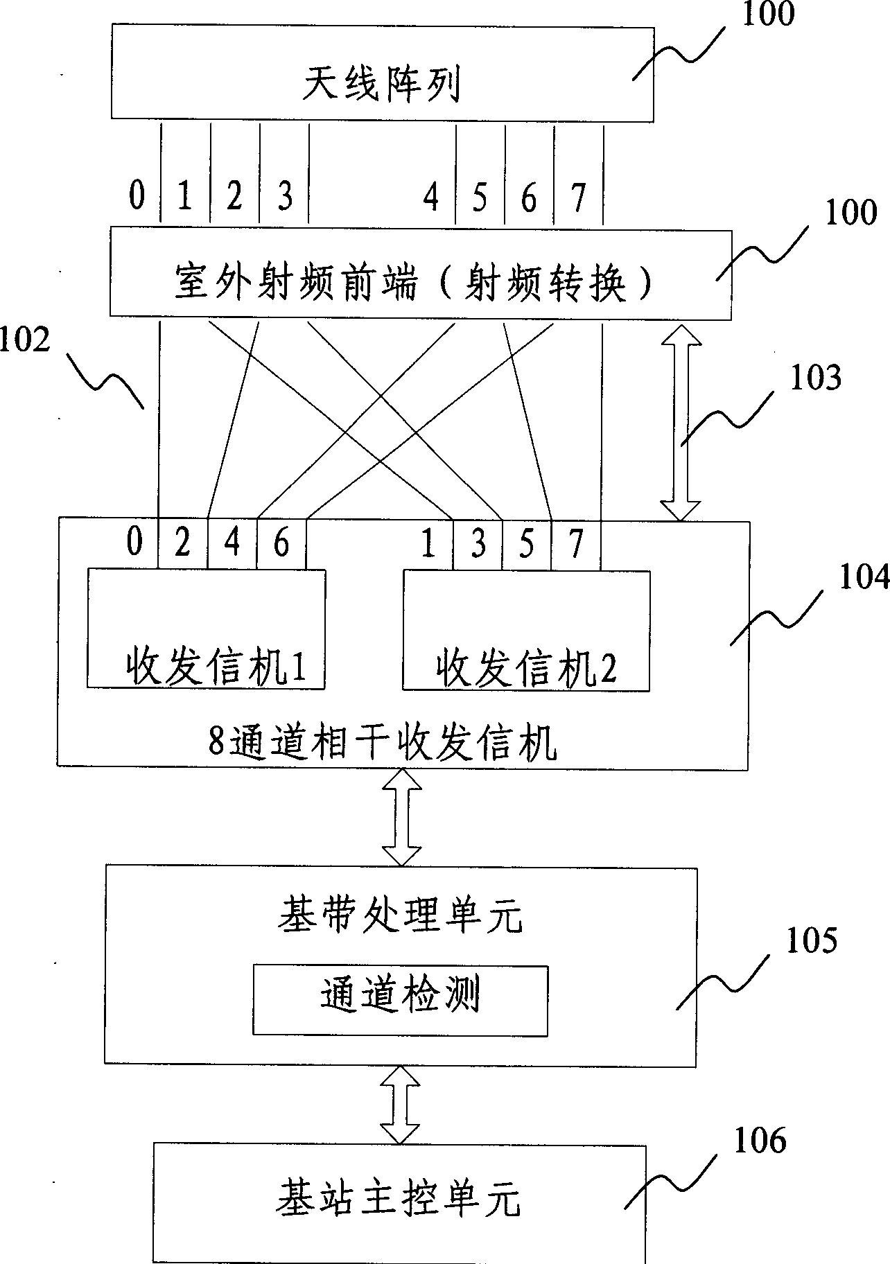
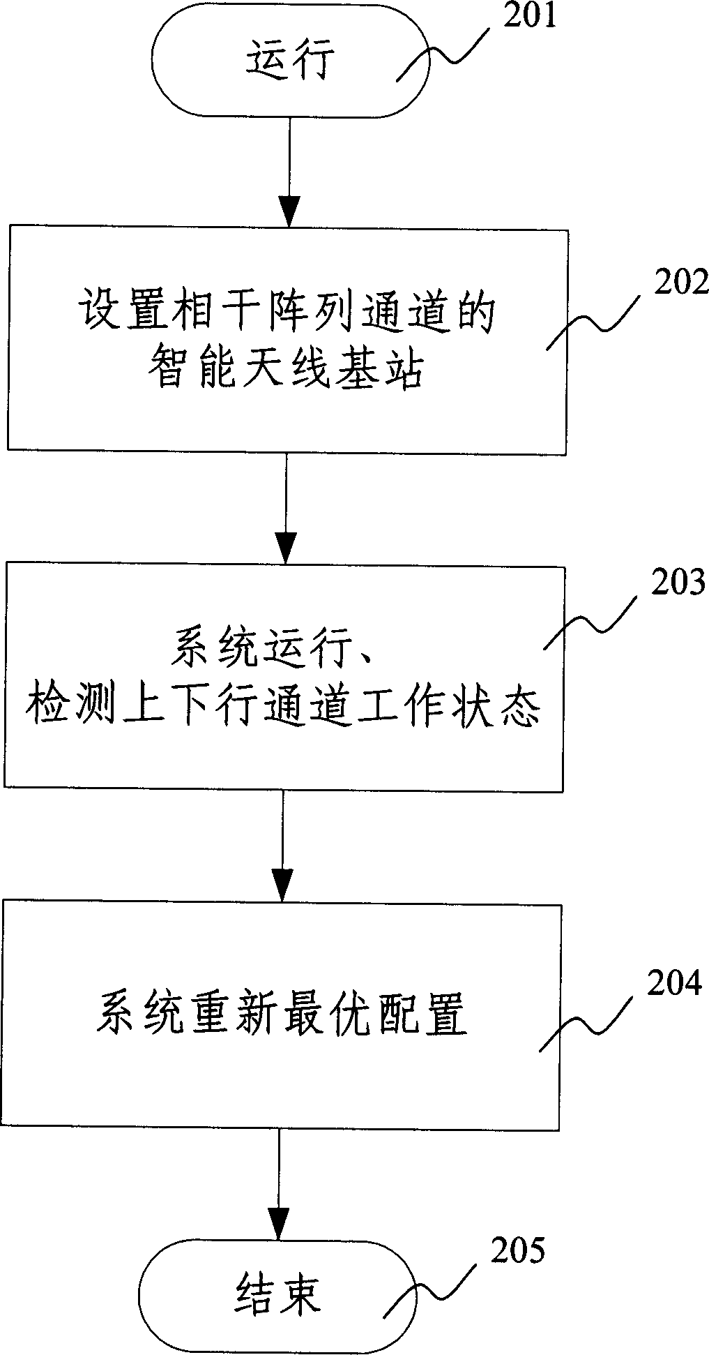
[0017] The following is based on figure 1 , figure 2 Examples of the present invention are given to further illustrate the method of the present invention.

[0018] figure 1 The structure of the coherent channel of the smart antenna base station array using the method of the present invention is shown. It mainly includes an antenna array 100 (the distance between the antenna arrays is less than one wavelength) and an outdoor radio frequency front end (the radio frequency front end includes 8 downlink power amplifiers and uplink low noise amplifiers, wherein the power of two power amplifiers is The gain is relatively large, corresponding to the 0th and 1st channels of the two transceivers, in case of single-channel high-power transmission; the RF front-end also includes RF channel conversion when the RF channel signal from the transceiver does not correspond to the front-end circuit circuit, in case the failure of the array element occurs in the flexible configuration of tw...


PUM


Abstract

This invention relates to an optimal reconfiguring method after the intelligent aerial losing, which comprises the following steps: a) setting intelligent aerial base station which makes up the coherent array channel; b) the base station will operate and check the working condition of the transmitting-receiving channel in the array channel, including generating the ascending and descending channel checking signal and measuring the channel response signal; c) checking the loss ascending and descending channel signals; d)allocating the system again according to the present condition, making the property optimal. By said method, when the array element loss, the system can check working condition if the hardware bug not sweep to the whole resource.

Description

technical field [0001] The invention relates to a method for system reconfiguration after the failure of the array elements in the array channel of the smart antenna system in the field of mobile communication, in particular to a method for maintaining the system after the partial failure of the array channel of the smart antenna base station, which is suitable for equidistant line arrays and uniform circular array systems. A method of array configuration for optimal performance. Background technique [0002] The smart antenna base station controls the direction and shape of the antenna beam by weighting the amplitude and phase of the signals received and transmitted by the array channel to achieve directional transmission and reception for desired users. The array channel adopts a uniform circular array with omnidirectional coverage or an equidistant line array with sectoral coverage. The downlink common channel of the base station is transmitted omnidirectionally within t...

Claims


Application Information

Patent Timeline
Patent Type & Authority Applications(China)
IPC IPC(8): H04Q7/30H04B7/04H04W88/08
Inventor 李景毅曾召华
Owner ZTE CORP
Why Eureka
Try Eureka