
Rotary displacement free speed changing device and rotary displacement free speed changing method

A speed change device, a free technology, applied in transmission devices, belts/chains/gears, mechanical equipment, etc., can solve the problems that the power cannot be compared with the gear speed change, the CVT transmission efficiency is low, and the automatic control is difficult, etc., to achieve light weight, Simple structure, good economic and social benefits

Inactive Publication Date: 2006-02-08
马平川
View PDF0 Cites 13 Cited by
  • Summary
  • Abstract
  • Description
  • Claims
  • Application Information

AI Technical Summary

Problems solved by technology

[0008] (2) It is extremely difficult for friction transmission CVT to realize high-power continuously variable transmission
[0009] (3) Low transmission efficiency of friction transmission CVT is inevitable
[0010] (4) The efficiency and power of friction transmission CVT cannot be compared with that of gear transmission
Its characteristic is that the mechanical transmission part continues to use the traditional stepped gearbox, but there are too many control parameters, and it is quite difficult to realize automatic control

Method used


Image

  • Rotary displacement free speed changing device and rotary displacement free speed changing method
  • Rotary displacement free speed changing device and rotary displacement free speed changing method
  • Rotary displacement free speed changing device and rotary displacement free speed changing method

Examples


Embodiment Construction

[0026] Accompanying drawing is the embodiment of the present invention

[0027] Below in conjunction with accompanying drawing, content of the present invention is further said:

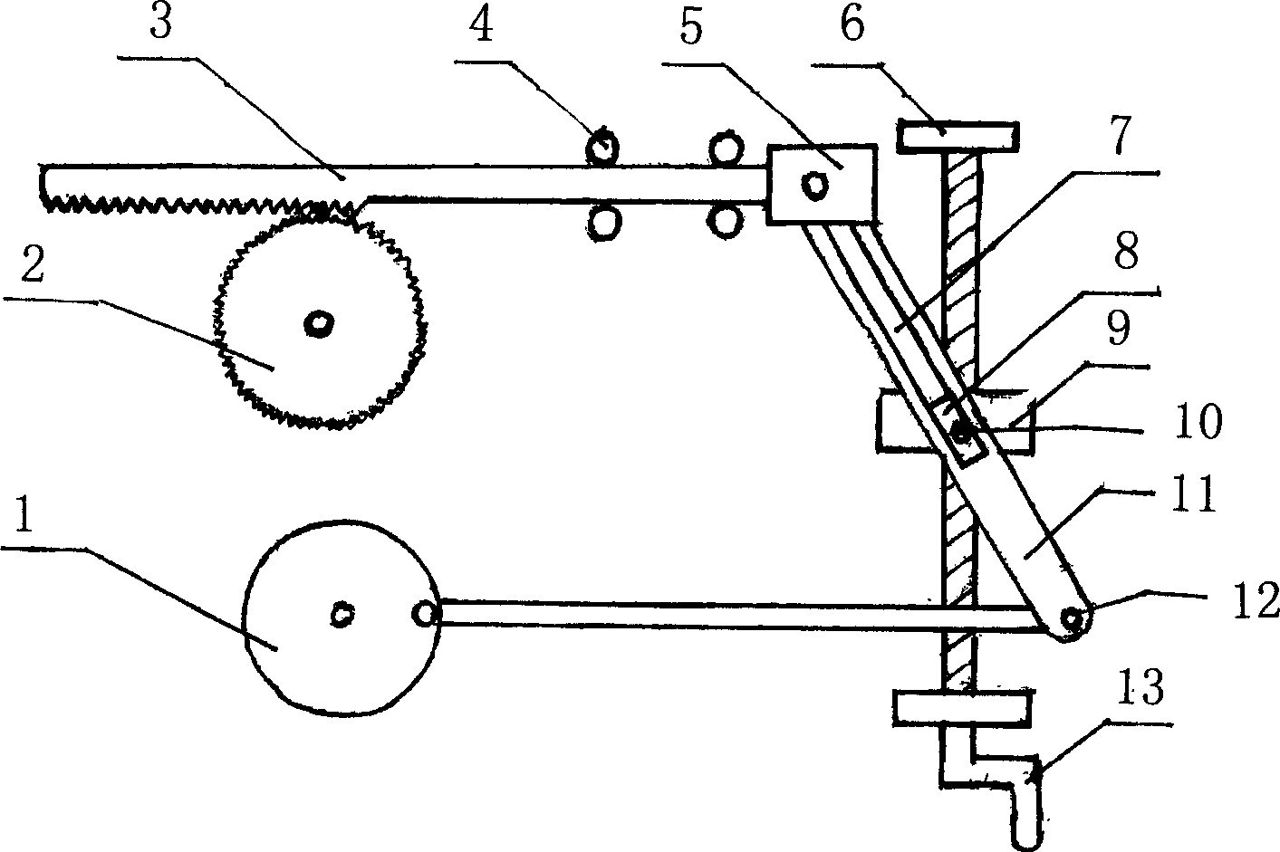
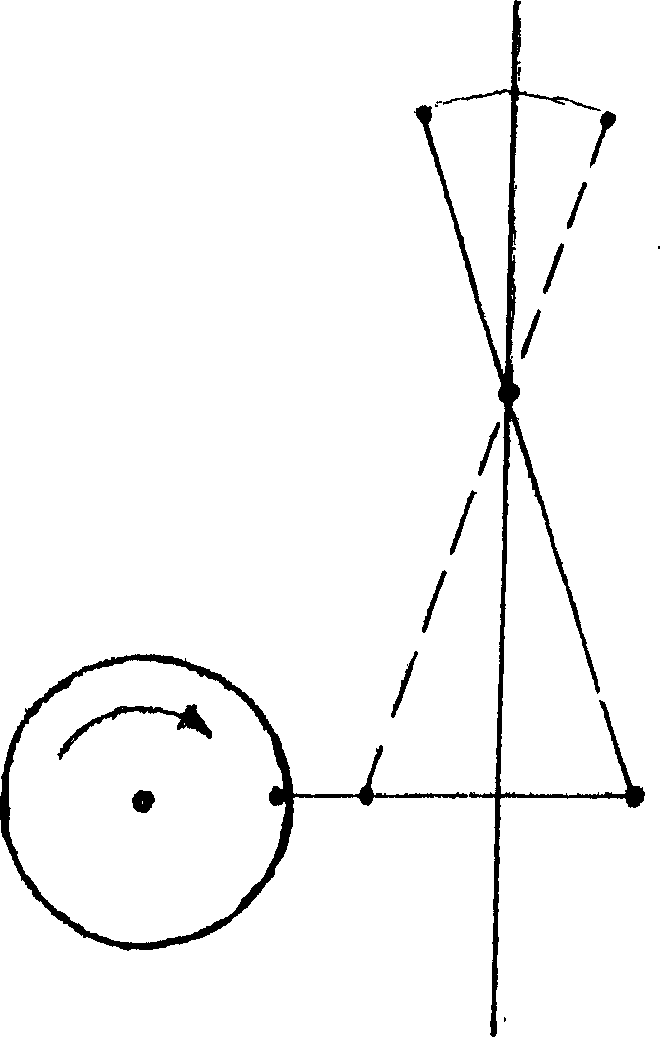
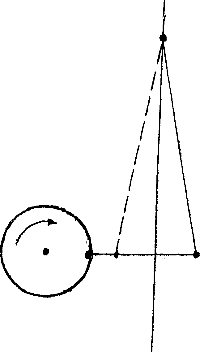
[0028] refer to figure 1 As shown, the crankshaft linkage mechanism 1 is connected to one end of the rotary shaft 11 through the hinge shaft 12, the rotary shaft 11 is provided with a sliding groove 7, and a sliding block 8 is installed in the sliding groove 7, and the sliding block 8 is fixed to the turbine 9 through the shaft 10. connection, the turbine 9 is inserted into the worm 13 for meshing connection, the two ends of the worm 13 are connected to the support seat 6, the other end of the rotary shaft 11 is connected to the rack end block 5 through a hinge shaft, and the rack end block 5 is connected to the rack 3 The two sides of the rack 3 are provided with guide wheels 4, and the rack 3 is meshed with the one-way gear 2 for transmission connection.

[0029] figure 2 As shown, when the sli...


PUM


Abstract

The present invention relates to free speed variator and speed varying method. The speed variator has crankshaft link rod mechanism connected via hinging shaft to the gyration shaft, block set inside the slide slot in the gyration shaft and connected via shaft to worm gear, worm with ends connected to the bearing seat, gyration shaft connected with toothed block via the hinging shaft, toothed block connected to the rack, guide wheels on two sides of the rack, and rack connected with ratchet. The speed varying method includes converting the rotation the crankshaft link rod mechanism inputs into gyration via the gyration shaft; driving the rack to reciprocate with the gyration shaft; and driving the ratchet to output rotation with the rack. The present invention has hard connected mechanical transmission mode to control rotation speed and transmission ratio for free change and output, has simple structure, low cost and other advantages, and may be used in vehicle, lathe, etc.

Description

technical field [0001] The invention relates to a speed change device in mechanical engineering, and is especially suitable for a rigidly connected stepless rotary displacement free speed change device and a rotary displacement free speed change method thereof. Background technique [0002] The existing speed change devices are mainly divided into three categories, one is gear transmission speed change, this kind of speed change has large volume, heavy weight, large processing volume, and inconvenient maintenance; the other is soft connection transmission speed change, this kind of speed change is reliable Poor, insufficient rigidity, easy to slip; Another category is to use friction transmission to change speed. This kind of speed change has high heat generation and is easy to burn out the transmission parts. The continuously variable transmission (CVT) was first invented by the Dutchman VanDoorne's. . The continuously variable transmission system does not use gears to cha...

Claims


Application Information

Patent Timeline
IPC IPC(8): F16H37/12
Inventor 马平川
Owner 马平川
Learn More