Optical fiber grating displacement sensor

A technology of displacement sensor and optical fiber grating, which is applied in the field of sensing, can solve the problems of poor long-term stability and susceptibility to electromagnetic interference, etc., and achieve the effect of convenient construction and installation, low cost and small size

Inactive Publication Date: 2006-03-08
DALIAN UNIV OF TECH
View PDF0 Cites 32 Cited by
  • Summary
  • Abstract
  • Description
  • Claims
  • Application Information

AI Technical Summary

Problems solved by technology

[0004] The purpose of the present invention is to provide a contact type optical fiber grating displacement sensor with simple structure, convenient layout, high precision and good long-term stability, which overcomes the shortcomings of traditional electrical displacement sensors, which are susceptible to electromagnetic interference and poor long-term stability, and can meet strong Displacement measurement in harsh environments such as electromagnetic radiation

Method used


Image

  • Optical fiber grating displacement sensor
  • Optical fiber grating displacement sensor

Examples


Embodiment Construction

[0011] The best embodiment of the present invention will be described in detail below in conjunction with technical solutions and accompanying drawings.

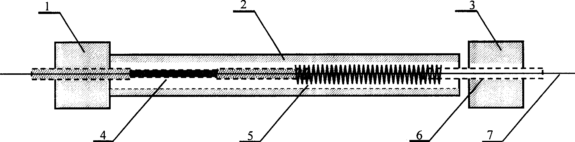
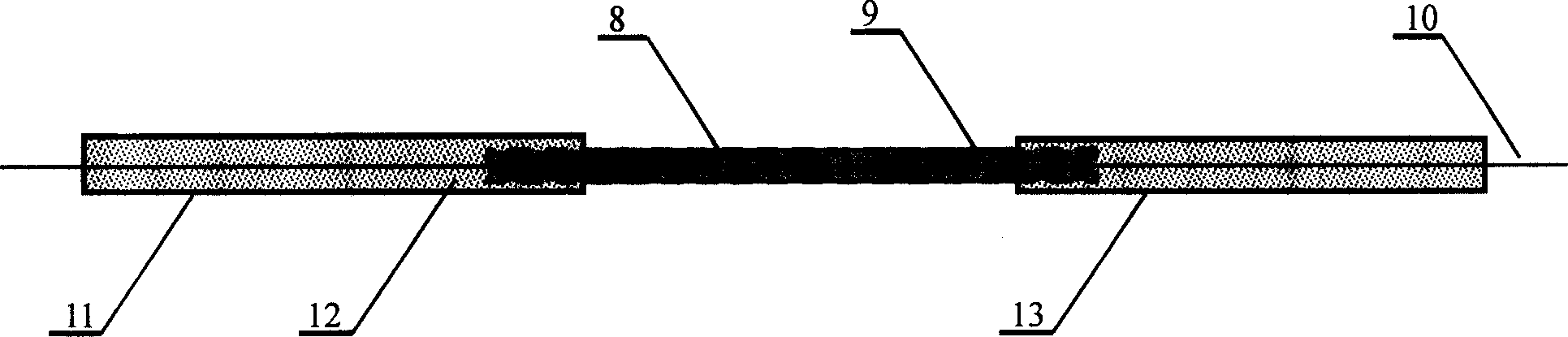
[0012] The fiber grating displacement sensor that the present invention proposes is shown in the attachment figure 1 As shown, the cross-sectional schematic diagram of the fiber grating strain sensor involved is shown in the attached figure 2 shown.

[0013] The specific method of fiber grating packaging is to first use a fiber coating machine to coat the fiber grating 8, then place it in a 0.5mm steel pipe 9, and use a precision fiber adjustment frame to adjust the position of the fiber grating 8, so that the fiber grating 8 is in the Then pour epoxy resin glue 12 into the central part, respectively install 1.2mm steel pipe 11 and 1.2mm steel pipe 13 on both sides of 0.5mm steel pipe 9, also pour epoxy resin glue 12, and complete the packaging process after the glue is cured.

[0014] The specific method of assembling th...


PUM


Abstract

This invention provides a contact type optical fiber grating displacement sensor, which contains support, protective steel pipe, spring and optical fiber grating strain sensor constructed of double steel pipe assembly structure, wherein the optical fiber grating packaged in 0.5mm steel pipe by epoxy resin and forming the optical fiber grating strain sensor with two 1.2mm steel pipe. Said invention has advantages of overcoming the shortage of current sensor of easy interfered by electromagnet and poor stability.

Description

technical field [0001] The invention belongs to the field of sensing technology and relates to a displacement sensor based on fiber grating technology. Background technique [0002] In civil engineering, the commonly used displacement sensors are strain gauge displacement sensors. It can be used in conjunction with secondary instruments such as strain gauges and digital voltmeters to measure static displacement in engineering tests. Since its core sensing element adopts electric strain gauge, it inevitably brings the shortcomings of being susceptible to electromagnetic radiation interference and poor long-term stability, and cannot meet the working needs of harsh working environments such as strong electromagnetic radiation. [0003] Fiber Bragg grating is a strain sensing element with excellent performance. It has the advantages of high sensitivity, small size, corrosion resistance, anti-electromagnetic radiation, flexible optical path, and is convenient for long-distance...

Claims


Application Information

Patent Timeline
Patent Type & Authority Applications(China)
IPC IPC(8): G01B11/02G01D5/26G01D5/353
Inventor 任亮李宏男
Owner DALIAN UNIV OF TECH
Why Eureka
Try Eureka