Light spectrum detecting device and method, and Raman amplifier feedback control device and method

A Raman amplifier and spectral detection technology, applied in the field of optical transmission, can solve the problems of large difference in signal optical power, difficult control of optical relay units, unsuitable for commercial use, etc., to achieve joint control, improve reliability and flexibility Effect

Active Publication Date: 2006-03-08
HUAWEI TECH CO LTD
View PDF0 Cites 4 Cited by
  • Summary
  • Abstract
  • Description
  • Claims
  • Application Information

AI Technical Summary

Problems solved by technology

The disadvantages of this control scheme are: 1. Raman amplifiers without control, when the line conditions change, cannot automatically adjust to adapt to link changes and require human intervention
2. If it is used in conjunction with an automatically controlled EDFA, it will be very difficult to control the entire optical relay unit
The disadvantage of t

Method used


Image

  • Light spectrum detecting device and method, and Raman amplifier feedback control device and method
  • Light spectrum detecting device and method, and Raman amplifier feedback control device and method
  • Light spectrum detecting device and method, and Raman amplifier feedback control device and method

Examples


Example Embodiment

[0051] Before describing the embodiments of the present invention in detail, the principle of gain spectrum control of the Raman amplifier is first introduced.

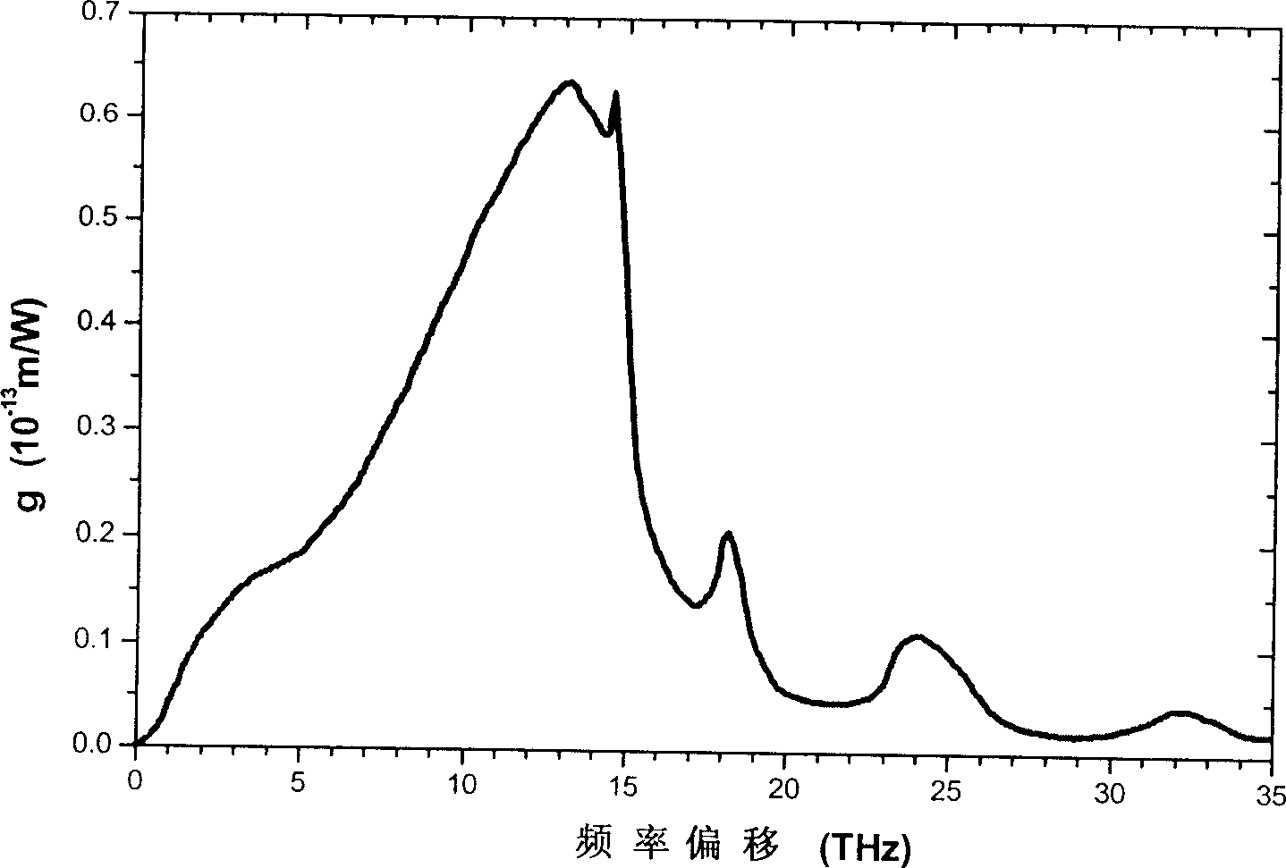
[0052] The control of the Raman amplifier is based on the working principle of the Raman amplifier. The Raman amplifier works based on the stimulated Raman scattering (SRS) effect in the optical fiber. The pump light of a single wavelength can only effectively amplify the signal light in the limited wavelength range (about 40nm), and the maximum is achieved where the frequency difference between the signal light and the pump light is 13.2THz (that is, the wavelength separation is about 100nm). Gain. In order to achieve gain within the entire transmission bandwidth, pump light of multiple wavelengths must be used. For example, there are at least two C BANDs and at least three C+L BANDs. We can adjust the gain of signal light of different wavelengths by adjusting the pump power of different wavelengths. This is the reason why...


PUM


Abstract

A spectrographic detector and method, and Raman amplifier feedback controller and method, said spectrographic detector used for detecting spectrographic with n wave length optical signal in transmission line, n is integer greater than 1, said detector containing at least one first splitter and one second splitter set in transmission line for splitting said optical signal, a filter with inclined insert loss spectrum, first power detector connected with said filter for detecting power of optical signal, second power detector connected with second splitter for detecting power of optical signal. Said invention can realize cooperative control.

Description

technical field [0001] The invention relates to the field of optical transmission, in particular to detection of spectrum and control of a Raman amplifier (RAMAN amplifier). Background technique [0002] figure 1 A typical structure of an optical transmission system is shown. Such as figure 1 As shown, the signal is sent into the optical fiber from the sending end and transmitted through a certain distance. Due to the loss of the optical fiber itself, the transmission signal will be attenuated, and the attenuated signal will be amplified and transmitted to the next stage through the first optical relay unit 11, so cycle. After several stages of transmission, the signal cannot continue to be transmitted downward due to the deterioration of the optical signal-to-noise ratio. At this time, an electrical relay unit 13 is used to recover the signal, and the optical signal output by the electrical relay unit has a good optical signal-to-noise ratio. Ratio (OSNR), so that the s...

Claims


Application Information

Patent Timeline
IPC IPC(8): G02F1/35G02F1/39G01J1/00G01J3/28H04B10/12H04B10/02H04B10/075H04B10/2537
Inventor 林东
Owner HUAWEI TECH CO LTD
Why Eureka
Try Eureka