
Process and flow for recovering hydrocarbon component from hydrocarbon containing gas

A hydrocarbon gas and hydrocarbon technology, applied in the field of recovery of hydrocarbon components, can solve problems that restrict the market promotion and application of oil and gas recovery projects, large processing capacity, and large installed capacity

Inactive Publication Date: 2006-03-22
宁波海曙洁源气体处理工程有限公司
View PDF0 Cites 4 Cited by
  • Summary
  • Abstract
  • Description
  • Claims
  • Application Information

AI Technical Summary

Problems solved by technology

Just because of the existence of the above factors, the regeneration and recovery part of the oil and gas recovery device in the prior art often has a large processing capacity, and is idle most of the time, the utilization rate of the device is not high, the installed capacity of the power equipment in the device is large, and the efficiency is low , high energy consumption
[0005] The above-mentioned defects in the existing adsorption process have restricted the market promotion and application of oil and gas recovery projects to a large extent, because if environmental protection and social benefits are not considered, and investment companies simply weigh the economic benefits of oil and gas recovery, this kind of project lacks sufficient Therefore, the social benefits of such projects in reducing air pollution and protecting the environment cannot be reflected

Method used


Image

  • Process and flow for recovering hydrocarbon component from hydrocarbon containing gas
  • Process and flow for recovering hydrocarbon component from hydrocarbon containing gas
  • Process and flow for recovering hydrocarbon component from hydrocarbon containing gas

Examples


Embodiment Construction

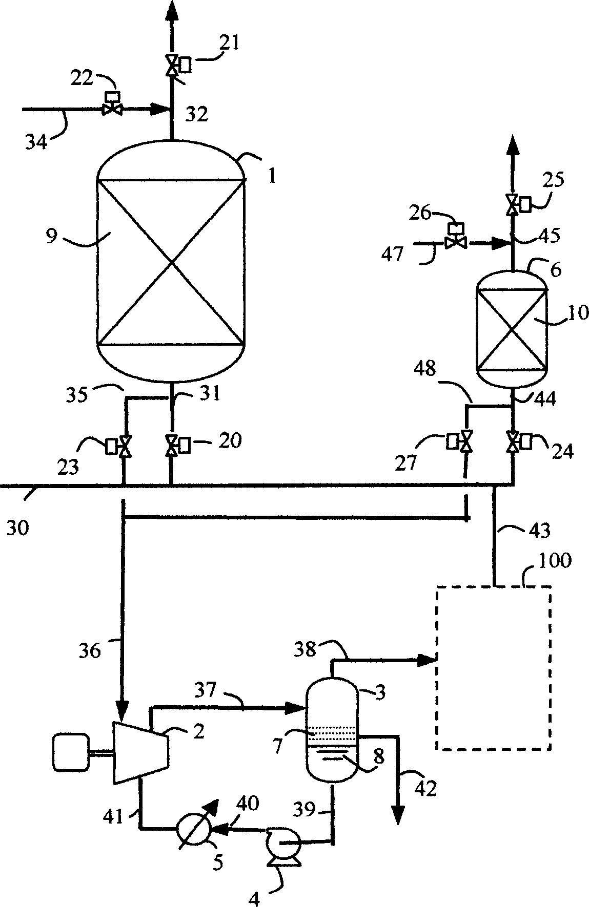
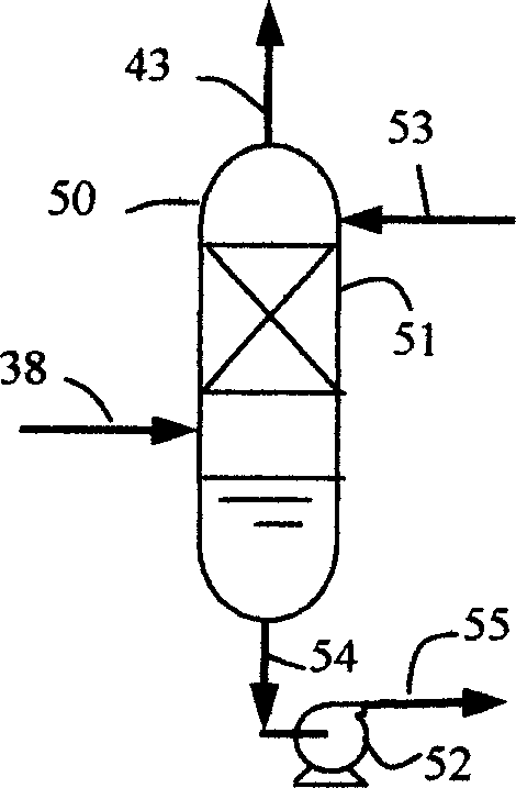
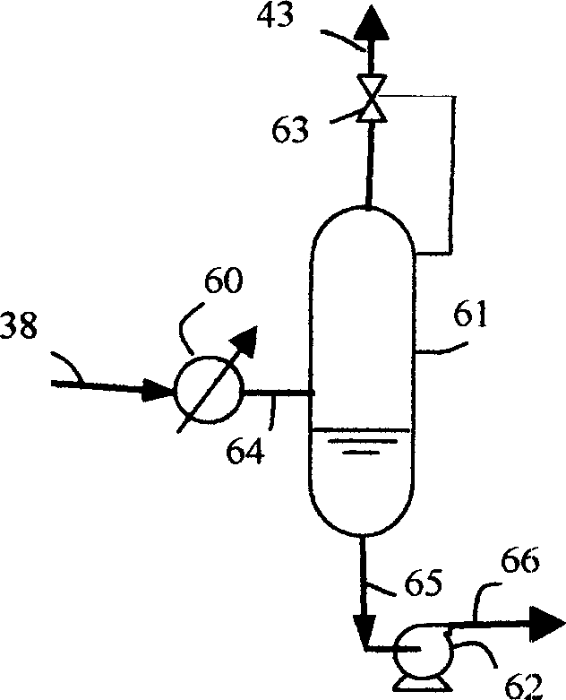
[0030] exist figure 1In the flow process shown, the first adsorption tank (1) and the second adsorption tank (6) are two adsorption devices filled with solid adsorbent (activated carbon) bed (9) and bed (10) inside, containing hydrocarbon One end of the inlet pipeline (30) where the gas-like gas enters the oil vapor recovery device is connected to the discharge source (not shown in the figure), and the other end is connected to the first adsorption tank (1) and the second adsorption tank through the pipeline (31) and the pipeline (44) respectively. The entrance of (6) is connected. One end of the pipeline (32) communicates with the outlet of the first adsorption tank (1), and the other end communicates with the atmosphere. One end of the pipeline (45) communicates with the outlet of the second adsorption tank (6), and the other end communicates with the atmosphere. On the inlet pipeline (31), pipeline (44) and outlet pipeline (32), pipeline (45) of the adsorption tank, on-of...


PUM


Abstract

Adsorption process is adopted in recovering hydrocarbon component from hydrocarbon containing gas. The working day is divided into two job stages, in the first stage, the first adsorption tank is in adsorption state while the second one in regeneration state; and in the second stage, the second adsorption tank is in adsorption state while the first one in regeneration state. These two long job stages are utilized fully for vacuum and stripping desorption regeneration of these two adsorption tanks and recovering the desorbed hydrocarbon component. Prolonging the desorption regeneration time can reduce the size of the regeneration and recovery parts, lower the investment and the running power consumption.

Description

technical field [0001] The invention relates to a process and process flow for recovering hydrocarbon components from the mixed gas of hydrocarbon components and air released during the filling process of light hydrocarbon liquids. Background technique [0002] During the process of filling light hydrocarbon liquids (such as gasoline, kerosene, crude oil, solvent oil, benzene products, etc.) Volatilizes from the liquid and forms a mixed gas of hydrocarbon components and air (hereinafter referred to as hydrocarbon-containing gas) with the air in the container. With the filling of the hydrocarbon liquid into the container, the hydrocarbon-containing gas produced Gas will be forced out of the container. If it is not recycled, it will not only cause waste of resources, but also pollute the atmosphere and increase the risk of fire and explosion. Since the 1960s, countries around the world have legislated and formulated emission standards to limit the unorganized emission of thi...

Claims


Application Information

Patent Timeline
IPC IPC(8): C10G5/02
Inventor 张国瑞
Owner 宁波海曙洁源气体处理工程有限公司
Learn More