Image interference photoetching method using end acousto-optical deflector and its system

An acousto-optic deflector and imaging interference technology, which is applied in the improvement field of imaging interference lithography technology, can solve the problems of low exposure efficiency, unfavorable popularization and application, and too little optimization and practical research, so as to improve exposure efficiency and benefit Optical path adjustment, the effect of improving laser utilization

Inactive Publication Date: 2006-03-29
INST OF OPTICS & ELECTRONICS - CHINESE ACAD OF SCI
View PDF0 Cites 9 Cited by
  • Summary
  • Abstract
  • Description
  • Claims
  • Application Information

AI Technical Summary

Problems solved by technology

The general imaging interference lithography method is to use lasers, beam splitters, mirrors, spatial filters, beam expander collimators, masks, imaging optical systems and resist substrates to form imaging interference lithography systems, literature Xiaolan Chen and S.R.J.Brueck, Imaging interferometric lithography for arbitrary patterns, SPIE Proceedings Vol.3331, 214-224, 1997 and literature S.R.J.Brucek, Imaging interferometric lithography, Microlitho

Method used


Image

  • Image interference photoetching method using end acousto-optical deflector and its system

Examples


Embodiment Construction

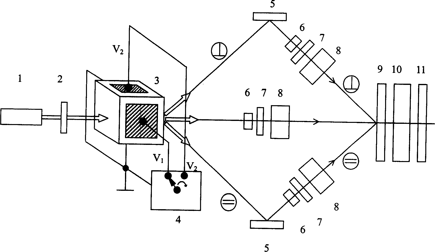
[0018] Such as figure 1 As shown, the imaging interference lithography system adopting an acousto-optic deflector of the present invention includes a laser 1, an electric shutter 2, an acousto-optic deflector 3, an acousto-optic power supply 4, a total reflection mirror 5, a beam expander 6, and a spatial filter 7, collimation system 8, mask 9, imaging optical system 10, resist substrate 11, acousto-optic power supply 4 is added to the ultrasonic driving voltage V on the acousto-optic deflector 3 1 =V 2 = 0, the laser beam emitted by the laser 1 passes through the electric shutter 2, directly passes through the acousto-optic deflector 3, expands the beam by the beam expander 6, and becomes parallel after being filtered by the spatial filter 7 and collimated by the collimation system 8 The light illuminates the mask 9, and the mask 9 is imaged onto the resist substrate 11 by the imaging optical system 10, so as to realize the vertical exposure of the low-frequency component of...


PUM


Abstract

The present invention relates to an imaging interference photoetching method by adopting one acousto-optic deflector and its system. It is characterized by that said invention only uses one acousto-optic deflector to make laser beam sent out by laser produce deflection, and utilizes the control of exposure intensity and exposure dose and utilizes the change of ultrasonic frequency to real-time control deflection angle size so as to implement triple exposure required for imaging interference photoetching process and raise exposure efficiency and resist pattern quality.

Description

technical field [0001] The invention relates to an imaging interference lithography method and system using an acousto-optic deflector, which belongs to the improvement of the imaging interference lithography technology. Background technique [0002] Imaging interference lithography is a new lithography technology that uses multiple exposures with different spatial frequency components to incoherently superimpose to improve the resolution of lithography. The general imaging interference lithography method is to use lasers, beam splitters, mirrors, spatial filters, beam expander collimators, masks, imaging optical systems and resist substrates to form imaging interference lithography systems, literature Xiaolan Chen and S.R.J.Brueck, Imaging interferometric lithography for arbitrary patterns, SPIE Proceedings Vol.3331, 214-224, 1997 and literature S.R.J.Brucek, Imaging interferometric lithography, Microlithography World, Winter 1998, 2-10 introduced the principles and techniq...

Claims


Application Information

Patent Timeline
IPC IPC(8): G03F7/20G02F1/33G02B27/60
Inventor 张锦冯伯儒宗德蓉
Owner INST OF OPTICS & ELECTRONICS - CHINESE ACAD OF SCI
Why Eureka
Try Eureka