Permanent magnet type electric rotating machine and wind turbine electric power generation system
一种永久磁铁、旋转电机的技术,应用在风能发电、风力发动机、风力发动机的控制等方向,能够解决不能避免轴方向的增加等问题,达到提高冷却效率的效果
- Summary
- Abstract
- Description
- Claims
- Application Information
AI Technical Summary
Problems solved by technology
Method used
Image

Examples
Embodiment 1
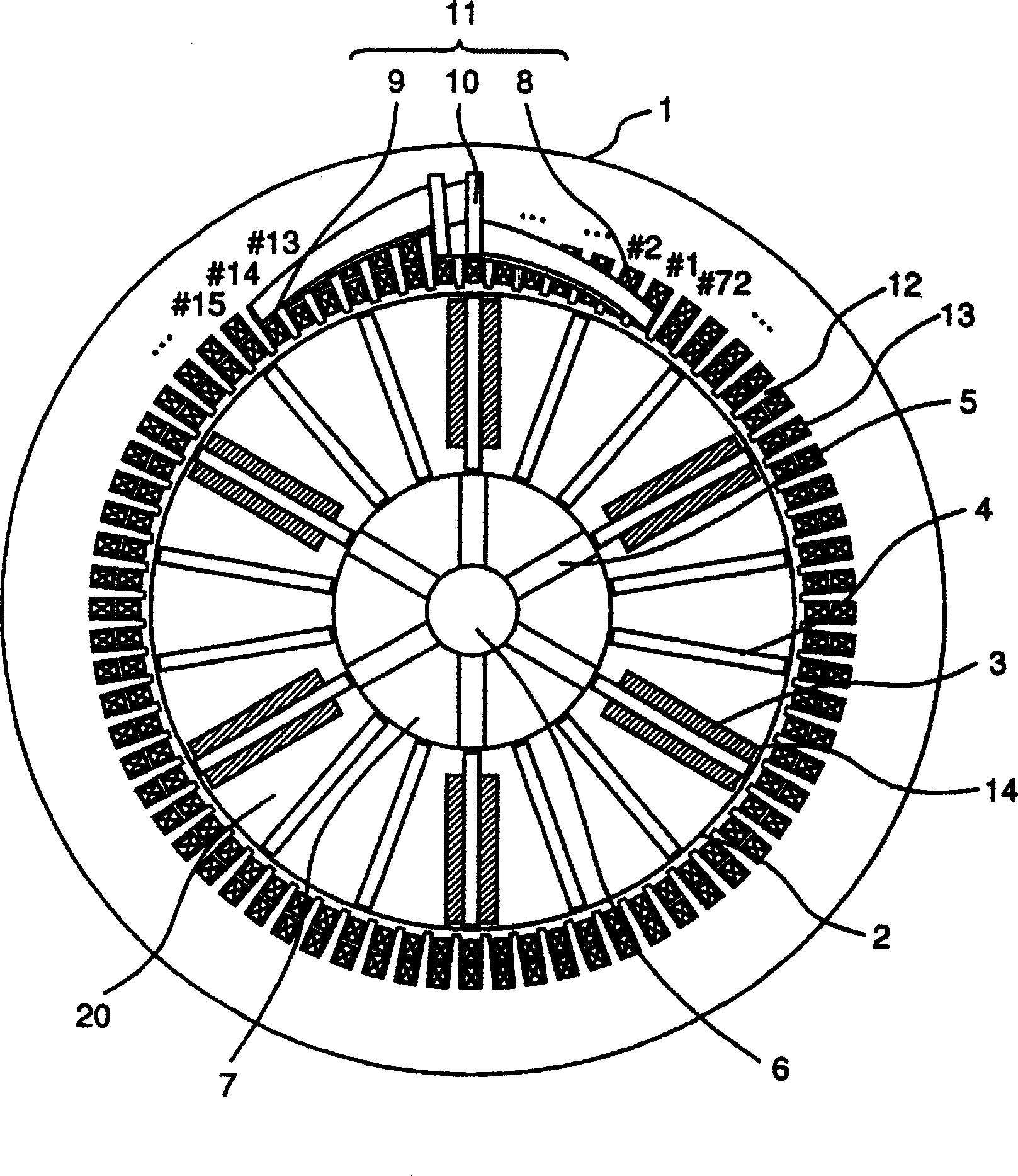
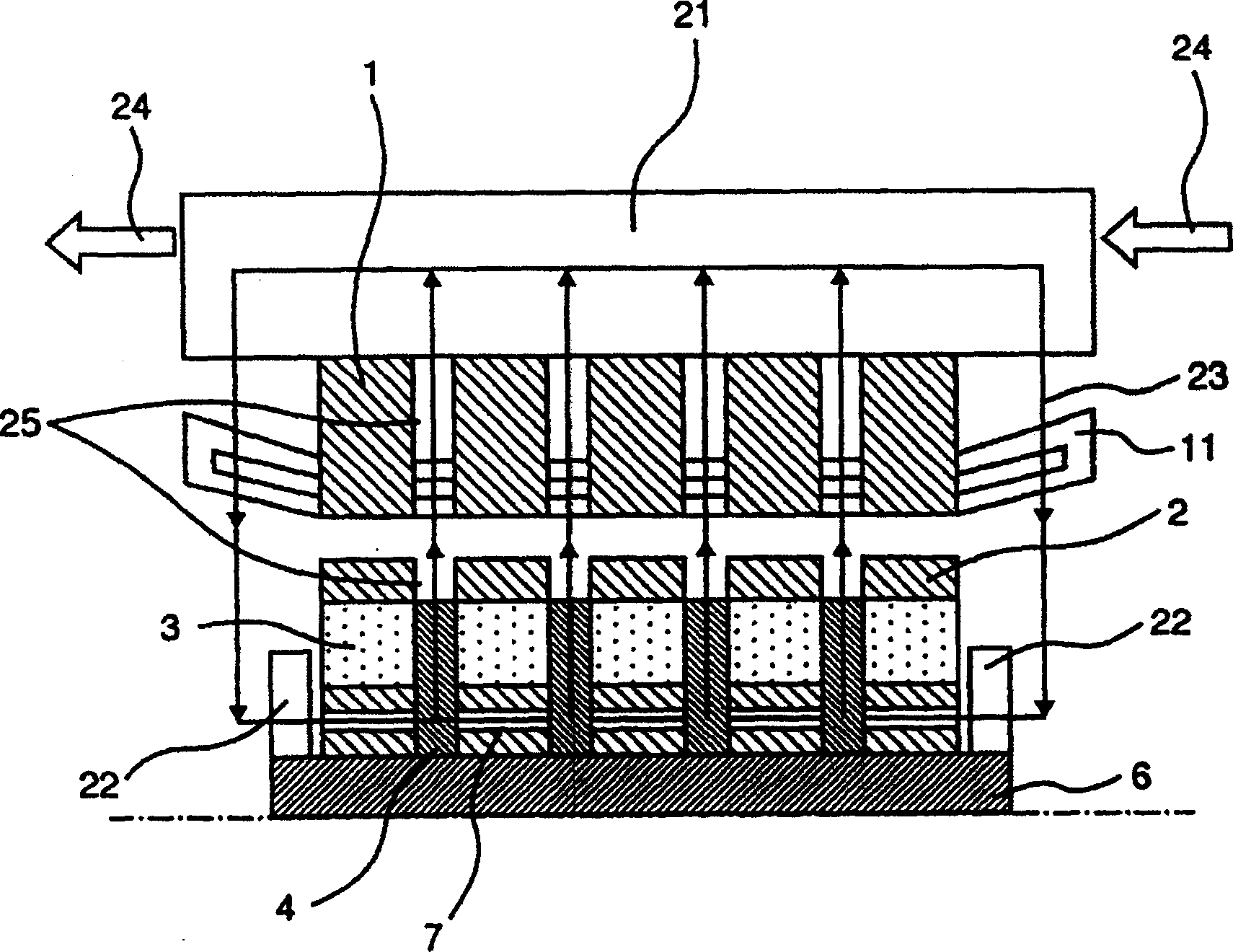
[0032] figure 1 It is a cross-sectional view of a generator end portion of a 6-pole, 72-slot permanent-magnet rotating electrical machine according to Embodiment 1 of the device of the present invention. This machine is suitable for wind power generators of several MW level, allowing the speed of 1000-2000rpm. The stator 1 is a distributed winding stator in which coils 11 are wound around stator teeth 12 in a distributed manner. The coil 11 is arranged so as to be wound with a 3-phase winding of UVW, and is arranged so as to have 6 poles in a 72-slot electrical system. In addition, the coil 11 is arranged as an upper coil 8 and a lower coil 9 in the stator slot 13 between the stator teeth 12 and is constituted by a coil end 10 . In Example 1, the coil 11 is wound in what is called a full-pitch winding, on the stator slot 13 coming out of the lower coil 9 of slot #1 of #1 to #72 slots suitably attached in a counterclockwise direction The coil 11 is set to enter the upper coi...
Embodiment 2
[0044] Figure 16 It is a cross-sectional view of a generator end of a 6-pole, 72-slot permanent magnet rotating electrical machine according to Embodiment 2 of the present invention. The stator 100 is a distributed winding stator in which coils 11 are distributed and wound on stator teeth 12 . The coil 11 is arranged so as to be wound with a 3-phase winding of UVW, and is arranged so as to have 6 poles in a 72-slot electrical system. In addition, the coil 110 is arranged as the upper coil 8 and the lower coil 9 in the stator slot 13 between the stator teeth 12 and is constituted by the coil end 10 . In Embodiment 1, the coil 11 is wound in what is called a short-pitch winding, the coil coming out of the lower coil 9 of the #1 slot suitably attached in the counterclockwise direction to #1 slot #1 to #72 slots of the stator slot 13 11, is set to enter the upper coil 8 of the #11 slot that adds 10 less than 12 obtained by dividing the slot number 72 by the pole number 6. In t...
Embodiment 3
[0046] Figure 17 It shows an example of applying the rotating electric machine of the present invention to a wind power generation system. The rotary electric machine 111 shown in Embodiment 1 and Embodiment 2 is connected to a windmill 112 via a speed increasing gear 113 and installed in a windmill nacelle 114 . Furthermore, the rotary electric machine 111 is connected to an electric power grid 116 via a power source 115 to enable power generation operation. In addition, in the present invention, wind power is used as a power source, but water wheels, engines, turbines, etc., for example, can be adequately applied. It is most effective in the case of wind power generation where the installation place of the rotating electric machine is strictly limited. In addition, the windmill 112 and the rotary electric machine 111 may be directly connected.
[0047] The wind power generator rotary electric machine in the above-mentioned embodiment has the advantage that it can be cool...
PUM
 Abstract
Description
Claims
Application Information
 - R&D
- Intellectual Property
- Life Sciences
- Materials
- Tech Scout
- Unparalleled Data Quality
- Higher Quality Content
- 60% Fewer Hallucinations
Browse by: Latest US Patents, China's latest patents, Technical Efficacy Thesaurus, Application Domain, Technology Topic, Popular Technical Reports.
© 2025 PatSnap. All rights reserved.Legal|Privacy policy|Modern Slavery Act Transparency Statement|Sitemap|About US| Contact US: help@patsnap.com