
Sewing machine

A sewing machine and suture technology, which is applied to sewing machine components, sewing equipment, and program-controlled sewing machines, etc., can solve the problems of insufficient driving torque, the moving blade cannot move the suture reliably, and the torque becomes large. The effect of shortening the operating cycle

Inactive Publication Date: 2006-04-12
JUKI CORP
View PDF1 Cites 11 Cited by
  • Summary
  • Abstract
  • Description
  • Claims
  • Application Information

AI Technical Summary

Problems solved by technology

Therefore, in order to shorten the operation cycle of the sewing machine, it is preferable to increase the rotation speed of the pulse motor. However, if the rotation speed is increased, when using thick sutures or sutures made of hard materials, the drive of the pulse motor may be insufficient and the movement may occur. When the blade cannot move reliably and the suture cannot be cut properly
[0006] Also, normally, the presser foot is given a downward elastic force, and the pulse motor is driven to resist the elastic force to raise it. However, the downward elastic pressing force may be generated depending on the thickness of the fabric to be sewn or the type of fabric. Therefore, when the presser foot is raised and lowered, if the pressing force is increased, the torque when the presser foot is raised will be increased by resisting the pressing force and driven by the pulse motor
Therefore, if the pulse motor is driven at an excessively high speed, the driving torque may be insufficient, and the lifting operation of the presser foot may not be properly performed.
[0007] In addition, in solving the above-mentioned problems, it is considered to use a high-output drive motor, but at this time, there are problems of increasing the size of the drive motor and increasing the cost, and it cannot be realized.

Method used


Image

  • Sewing machine
  • Sewing machine
  • Sewing machine

Examples


Deformed example 1

[0139] The above-mentioned embodiment is based on the configuration in which the rotation speed mode of the pulse motor 13 is selected based on the input of the driving voltage of the solenoid 81 that drives the thread adjustment mechanism 80 through the controller 98, but the first modification The sewing machine can input the thickness of the sewing thread through the controller 98 (thread thickness information input means). And CPU91 reads the rotational speed mode selection program 93a from ROM93 based on the thickness of the suture thread input, and selects the rotational speed mode which produces the drive torque in tangential phase A from ROM93 according to the execution of this rotational speed mode selection program 93a, This driving torque is used to cut the inputted thick and thin sutures.

[0140] Therefore, according to Modification 1, according to the thickness of the suture input through the controller 98, the rotational speed mode data 93c that takes into accou...

Deformed example 2

[0142] Next, for the sewing machine of Modification 2, refer to Figure 10 To illustrate. here, Figure 10 This is a block diagram showing the configuration of main parts of a sewing machine according to Modification 2.

[0143] The sewing machine of Modification 2 performs sewing according to a predetermined sewing pattern, and the thickness of the sewing thread used for each sewing pattern is predetermined. That is, if Figure 10 As shown, the ROM 193 of the sewing machine stores, as sewing pattern storage means, sewing pattern data 193c corresponding to a plurality of sewing patterns and thicknesses of sewing threads used for sewing these sewing patterns. Furthermore, in the ROM 193, a plurality of rotational speed pattern data 193d defined based on the above-mentioned thickness of the suture and the rotational speed of the pulse motor 13 at the time of cutting the suture are stored.

[0144] In addition, in the ROM 193, a line thickness information acquisition program ...


PUM


Abstract

A seaming machine (10) comprises a cutter (4) for cutting suture line, a cloth press (20) for lifting compress foot (21), a pulse motor (13) driving the two devices, a ROM93 storing multiple rotation speed data (93c) defining the rotation speed of the pulse motor when the cutter cuts suture line, a rotation speed selector (as CPU91) for selecting the rotation speed data generating the drive torque capable of cutting suture line at least from the ROM, according to the suture line thickness input by a controller (98), relative to the drive voltage of a conchoids (81) driving a yarn change mechanism (80), and a drive controller (as CPU91) for controlling the rotary drive of the pulse motor according to the selected rotation speed data. The invention can optimize the rotation speed of the drive motor when cuts suture line to reduce rotation period.

Description

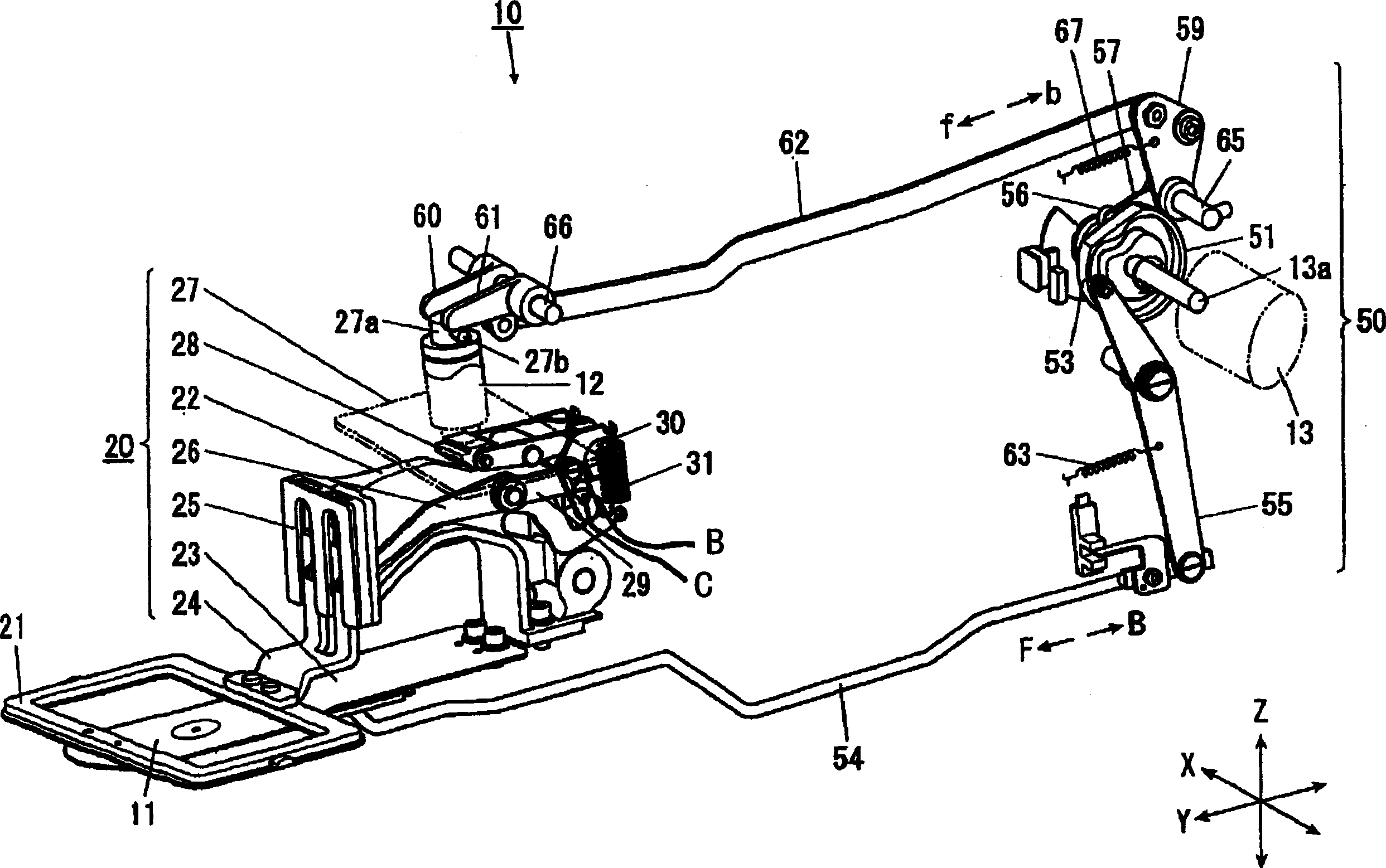
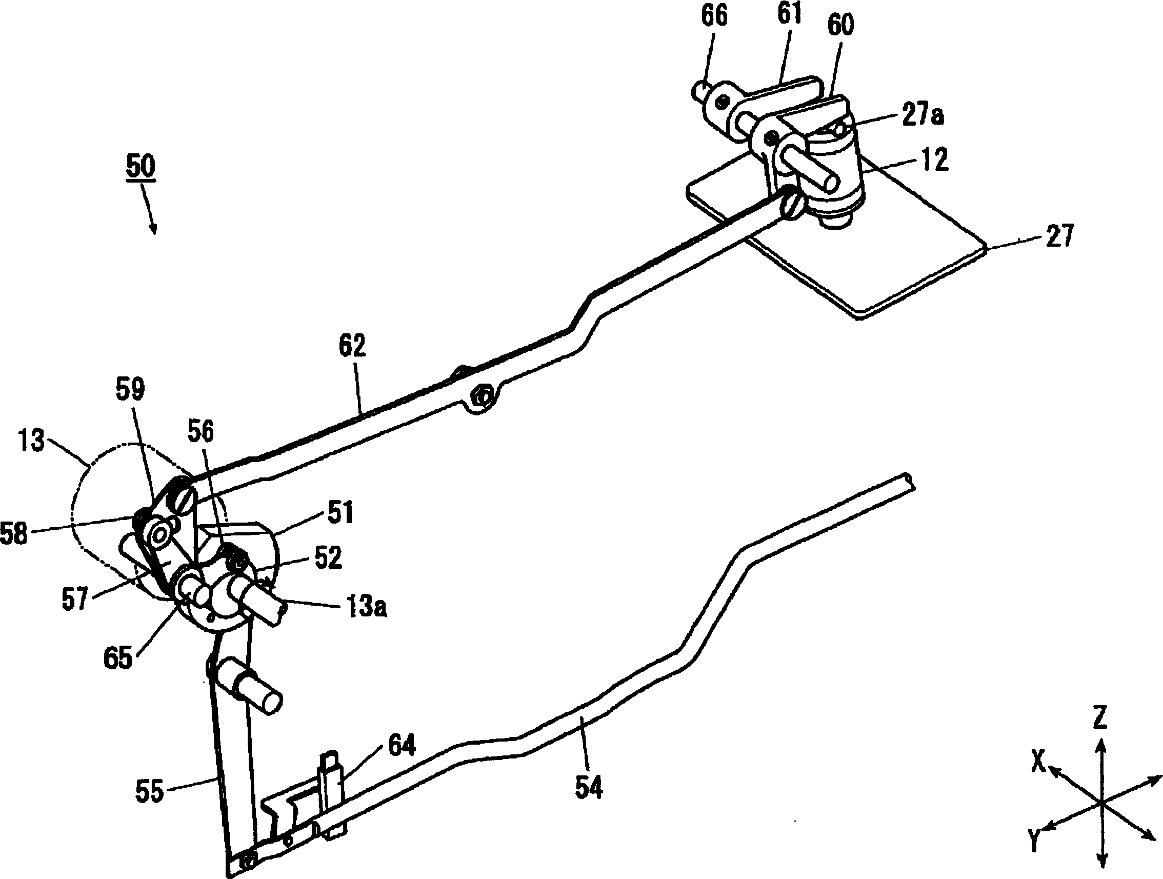
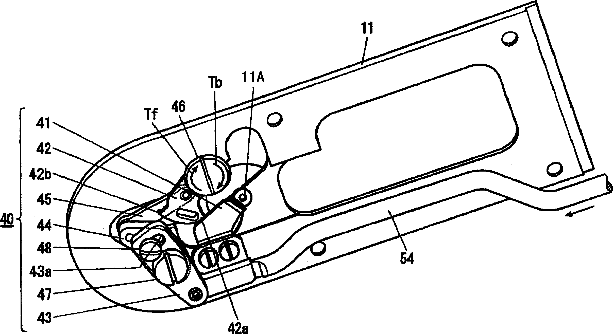
technical field [0001] The present invention relates to a sewing machine with a driving mechanism for sewing threads and a cloth pressing mechanism for raising and lowering a pressing foot. Background technique [0002] Conventionally, a known sewing machine has a drive mechanism for moving a movable blade to cut a suture, and a cloth presser mechanism for raising and lowering a presser foot, and these mechanisms are operated by a drive motor. Furthermore, in recent known sewing machines, both mechanisms are operated by controlling the rotation of a single drive motor. (For example, refer to Patent Document 1) [0003] In these sewing machines, for example, after sewing, based on the rotational drive of the above-mentioned drive motor, after the sewing thread is cut by the cutting mechanism, the presser foot of the cloth pressing mechanism is raised, and then the sewing machine is restarted. Lower the presser foot. Therefore, from the viewpoint of shortening the operating...

Claims


Application Information

Patent Timeline
Patent Type & Authority Applications(China)
IPC IPC(8): D05B19/12D05B29/00D05B65/02
CPCD05B19/12D05B29/02D05B37/06D05B47/04D05B65/02D05B69/30
Inventor 山岸正则
Owner JUKI CORP
Learn More