Heat exchanger

A technology for heat exchangers and fins, applied in the field of heat exchangers, can solve problems such as restrictions on weight reduction or miniaturization of heat exchangers, difficulty in performing leakage inspection of connecting parts, and limitations in installation locations or uses, and achieves simple manufacturing technology, The effect of excellent heat exchange performance, simplified manufacturing technology or manufacturing process

Active Publication Date: 2006-04-19
USUI KOKUSAI SANGYO KAISHA LTD
View PDF5 Cites 15 Cited by
  • Summary
  • Abstract
  • Description
  • Claims
  • Application Information

AI Technical Summary

Problems solved by technology

[0011] However, in the pipe body of Patent Document 2 or 3, due to the presence of spiral or radial fin members, bending with a small radius of curvature is difficult during bending, and the volume increases, making it difficult to arrange under a narrow floor. or the back of the device, etc.
In addition, in Patent Document 4, there is a problem with the strength of each thin-plate fin. When forming the insertion through hole or when the pipe body is inserted through, the thin-plate fins are likely to be deformed or damaged, and it is necessary to be careful and labor-intensive.
In addition, using the mode of inserting the through-pipe main body into the

Method used


Image

  • Heat exchanger
  • Heat exchanger
  • Heat exchanger

Examples


Example Embodiment

[0097] Example 1

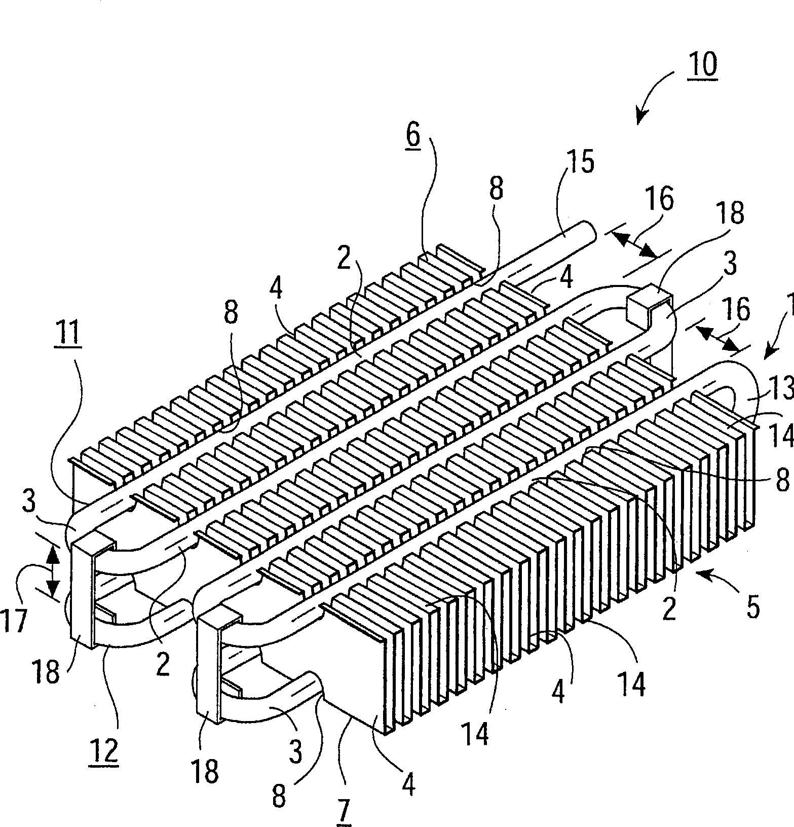
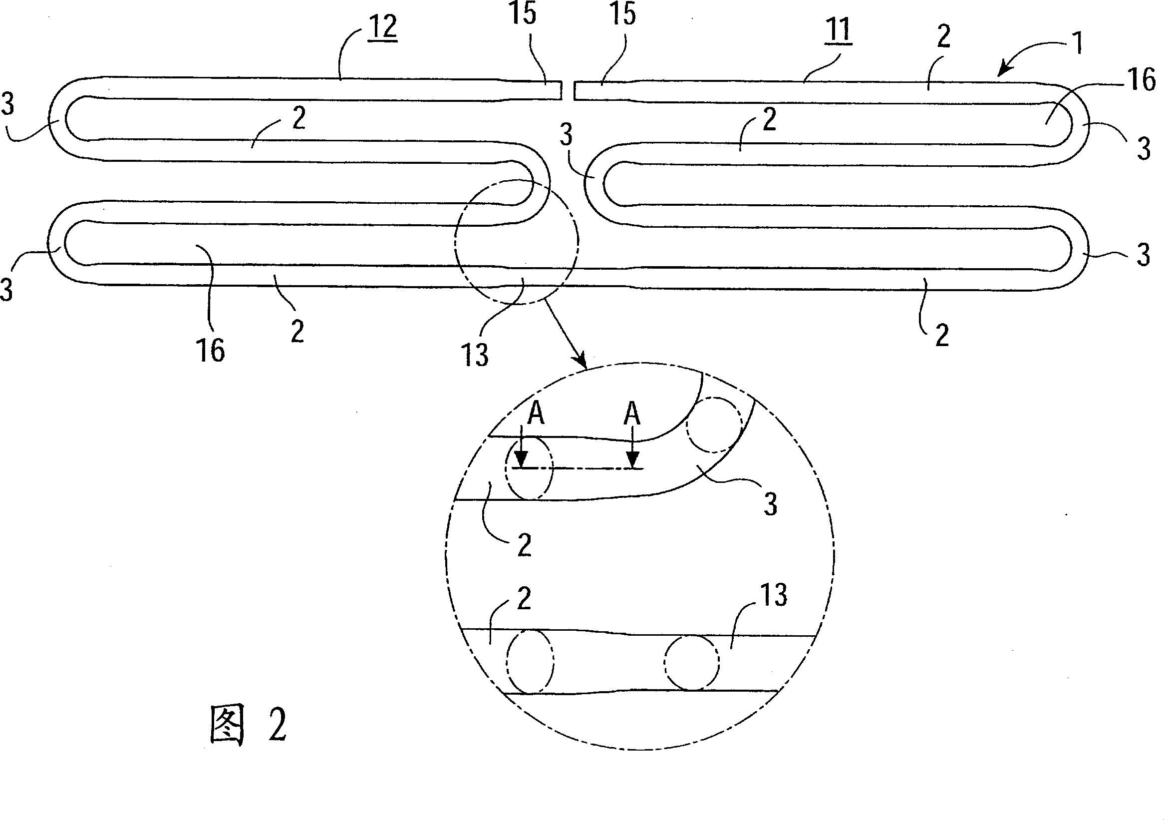
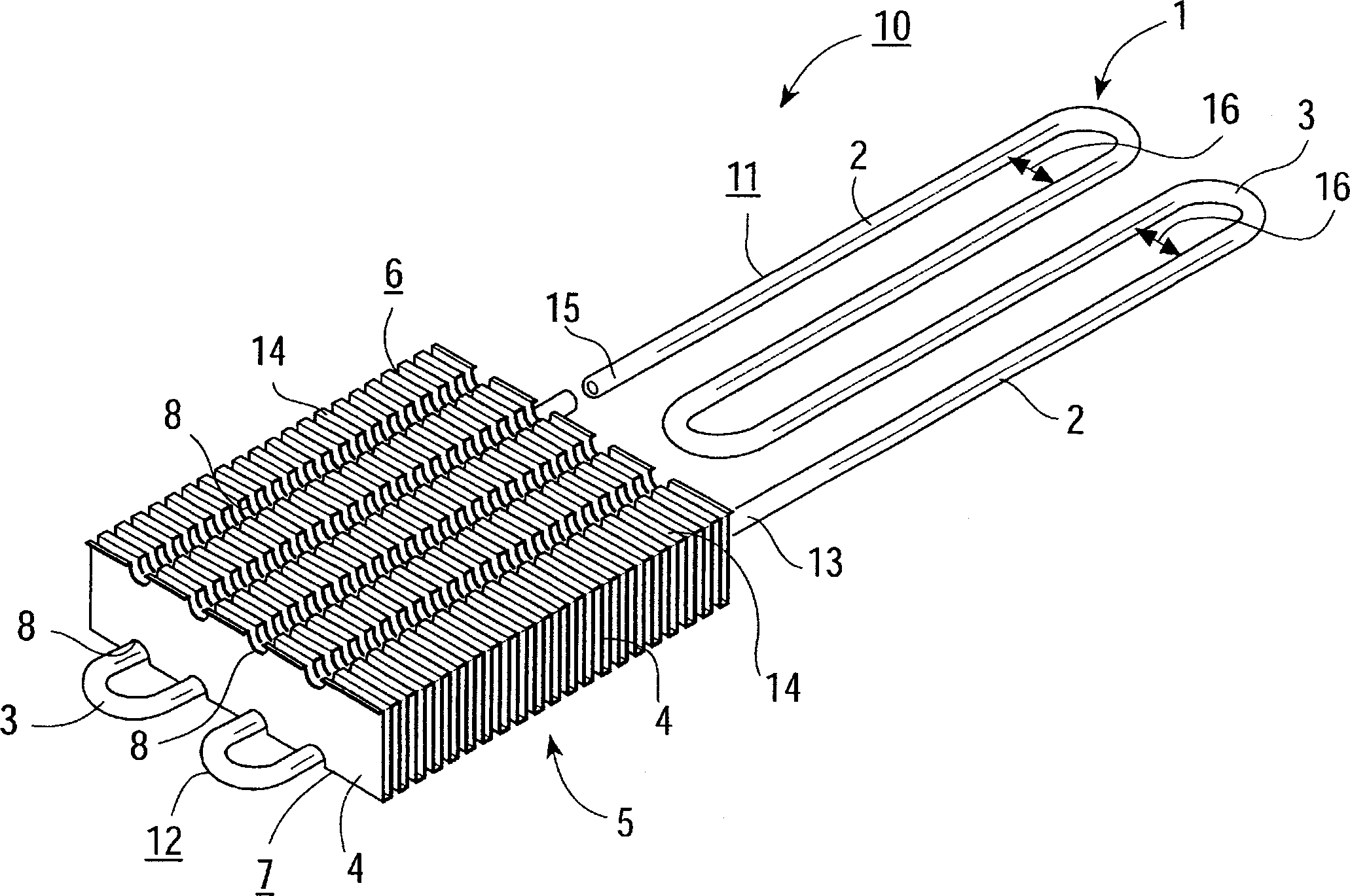
[0098] Embodiment 1 in which the heat exchanger of the present invention is implemented as a fuel pipe arranged under the floor of an automobile is utilized Figure 1 to Figure 6 To describe it in detail, (1) is the main body of the serpentine pipe, and a pair of serpentine parts (11) and (12) are arranged to face each other with the insertion gap (17) of the fin member (5) separated. The parts (11), (12) are formed by a plurality of straight pipe parts (2) arranged in parallel at a desired opposing interval (16) and a bent part (3) connecting the plurality of straight pipe parts (2) . Furthermore, in the insertion gap (17) formed between the one group of serpentine parts (11) and the other group of serpentine parts (12), a fin member (5) is inserted and arranged, and the fins (5) are arranged in parallel. On the opposite end surfaces (6) (7) of the plurality of cooling fins (4), a plurality of rectangular engagement grooves (8) are arranged at certain int...

Example Embodiment

[0112] Example 2

[0113] In the above-mentioned embodiment 1, a metal pipe is bent to form a serpentine pipe main body (1) composed of a plurality of straight pipe parts (2), bent parts (3), and connecting pipes (13). In another different embodiment 2, the bent portion (3) and the connecting pipe (13) are formed by a U-shaped ventilation pipe, and a plurality of straight pipe portions (2) are formed by a single straight pipe. Furthermore, the plurality of straight pipe parts (2) are arranged at an opposing interval (16), each straight pipe part (2) is connected with a bent part (3), and connected to each other by brazing or welding, etc., respectively forming A pair of snaking parts (11), (12). Furthermore, a pair of meandering parts (11) and (12) arranged oppositely are connected by a connecting pipe (13) with the insertion gap (17) of the fin member (5) interposed therebetween. In addition, in order to facilitate arrangement in the engaging groove (8), the straight pipe p...

Example Embodiment

[0116] Example 3

[0117] In addition, in Examples 1 and 2, the fixing of the straight pipe portion (2) to the engaging groove (8) is through the clamping force of one serpentine portion (11) and the other serpentine portion (12), and the clip (18) Performed with clamping and fixing force. In order to make the fixing between the straight pipe part (2) and the engaging groove (8) more firm, in embodiment 3, when it is arranged in the engaging groove (8), as Figure 8 As shown, the straight pipe part (2) is formed into an ellipse shape, the short diameter part of the ellipse is smaller than the forming width of the engaging groove (8), and the long diameter part of the ellipse is smaller than the forming width of the engaging groove (8). Wide. Furthermore, when the elliptical straight pipe part (2) is arranged in the engagement groove (8), as Figure 8 As shown, it is arranged so that the major diameter of the ellipse is located in the direction of the bottom of the engagemen...


PUM


Abstract

A heat exchanger having excellent heat exchanging performance is obtainable by a simple production technique and at a low cost. This is achieved by providing a fin member and by increasing heat conductivity between the fin member and a meandering tube body. Further, the heat exchanger is made compact for high degrees of layout freedom, enabling the heat exchanger to be installed in a tight space. Engagement grooves (8) are provided in both end surfaces (6, 7), which are opposite to each other, of a fin member (5) in which fins (4) are parallelly arranged. Straight tube sections (2) are parallelly arranged, with gaps (16) in between, in the engagement grooves (8) of the fin member (5). The straight tube sections (2) are connected at bent sections (3). A pair of meandering sections (11, 12) is arranged opposite to each other with an insertion gap (17) of the fin member (5) in between. One (11) of the meandering sections and the other meandering section (12) are connected by a connection tube (13) to form a meandering tube main body (1). The straight tube sections (2) of the one meandering section (11) are arranged in the engagement grooves (8) in the one end surface (6) of the fin member (5) inserted and arranged in the insertion gap (17) between the one meandering section (11) and the other meandering section (12) of the meandering tube body (1), and the straight tube sections (2) of the other meandering section (12) are arranged and fixed in the engagement grooves (8) in the other end surface (7).

Description

field of invention [0001] The present invention relates to fluid cooling pipes such as fuel pipes and oil pipes for automobiles and general industrial use, EGR gas cooling devices, air conditioners for adjusting the temperature and humidity of living spaces, and other heat exchangers. , a heat exchanger with excellent heat exchange performance can be obtained at low cost. Background technique [0002] So far, there are fluid cooling pipes such as fuel pipes and oil pipes for automobiles and general industries, EGR gas cooling devices, air conditioners for adjusting the temperature and humidity of living spaces, and other heat exchangers. For example, as shown in Patent Document 1, on the fuel pipe for automobiles, a fuel cooler having tanks such as cooling water, refrigerant for automobile air conditioners, or other refrigerant liquids is connected, and oil materials, etc. flowing in the fuel pipes are connected. Allow to cool. However, on diesel engines, etc., since the f...

Claims


Application Information

Patent Timeline
IPC IPC(8): F28F1/32F25B39/00F28D1/047
Inventor 臼井正佳桥本康明林耕一石田重行小方哲夫天野长寿栗田浩二四元众
Owner USUI KOKUSAI SANGYO KAISHA LTD
Why Eureka
Try Eureka