Jib bed density distribution detector

A bed density and detection device technology is applied in the field of a jig washing bed density distribution detection device and a device for real-time detection of material density. Separation accuracy, reduction of material mismatch rate, and improvement of product quality

Inactive Publication Date: 2006-04-26
TAIYUAN UNIV OF TECH
View PDF0 Cites 6 Cited by
  • Summary
  • Abstract
  • Description
  • Claims
  • Application Information

AI Technical Summary

Problems solved by technology

However, due to technical inadequacy, the above-mentione

Method used


Image

  • Jib bed density distribution detector
  • Jib bed density distribution detector
  • Jib bed density distribution detector

Examples


Embodiment approach 1

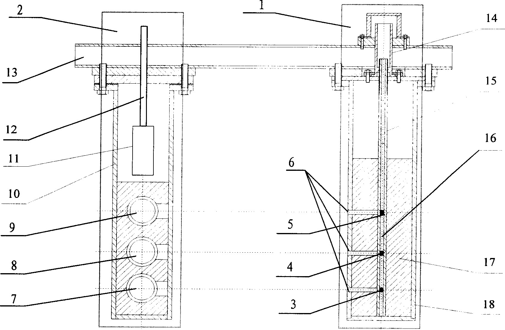
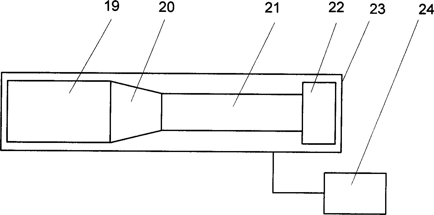
[0021] Embodiment 1: The device for detecting the material density of the jig multi-source gamma-ray bed is as follows: Figure 5 Placed in the jig machine bed, the distance between the gamma-ray radiation source assembly 1 and the photodetector assembly 2 is 600mm, the distance between the bottom gamma-ray radiation source 3 and the sieve plate of the jig machine is 90mm, and the bottom gamma-ray radiation source 3 and the middle layer gamma-ray The distance between the radiation source 4 is 100 mm, and the distance between the middle layer γ-ray radiation source 4 and the upper layer γ-ray radiation source 5 is 90 mm. After the photodetectors 7, 8, and 9 corresponding to the above-mentioned γ-ray radiation sources receive the incident particles attenuated by the coal seam, they are multiplied and amplified by the photomultiplier tube 21 for multiple times, and finally the photodetector assembly 2 figure 2 The subsequent circuit shown outputs an electrical pulse signal. The...

Embodiment approach 2

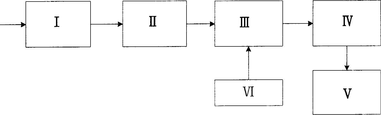
[0022] Embodiment 2: counting time by Figure 4 Controlled by the gate control signal shown: Calculate the bed density value of the jig machine in the loosening period of the upper, middle and lower three horizontal positions from the count value during the low level period of D1. Others are the same as Embodiment 1.

Embodiment approach 3

[0023] Embodiment 3: counting time by Figure 4 The gating signal shown is used to control: count at the same time during the low level period of D1 and D2, and calculate the bed density value of the loose period and the compact period of the jig in the upper, middle and lower three horizontal positions. Others are the same as Embodiment 1.


PUM


Abstract

The invention device a real-time detecting device of material density on the jigger layer, which consists of ª†-ray detector along the height distribution and back-end disposing circuit. The device provides a reliable detector of jigger inner layer density distribution condition, which realizes the visible statue of bed density distribution automatically.

Description

technical field [0001] The device for detecting density distribution of a jigging washing bed layer of the present invention belongs to the technical field of mechanical and electronic detection, and specifically relates to a device for real-time detection of material density on a jigging machine bed layer. technical background [0002] In the currently used jigging machine control system, the commonly used method is to use the buoy sensor to detect the heavy material layer of the jigging bed, detect the thickness of the heavy product bed, and control the discharge based on this, the goal is to maintain This bed thickness is stable. Even the Bardock Jig. Since the buoy can only detect the thickness of the material layer greater than a certain specific gravity, it cannot fully reflect the stratification state of the material layer in the jig machine. In recent years, a variety of state detection methods that can directly or indirectly reflect the stratification of the materi...

Claims


Application Information

Patent Timeline
IPC IPC(8): G01N9/24G01N23/12
Inventor 熊诗波魏晋宏符东旭杜岚松贾建新李文英杨洁明
Owner TAIYUAN UNIV OF TECH
Why Eureka
Try Eureka