
Distributed microstructure optical fiber gas sensing system and sensing method

A technology of micro-structured optical fiber and sensing system, which is applied in the fields of analyzing materials, measuring color/spectral characteristics, and analyzing materials through optical means. and permeable gas absorption chambers

Inactive Publication Date: 2006-05-03
重庆工学院
View PDF0 Cites 13 Cited by
  • Summary
  • Abstract
  • Description
  • Claims
  • Application Information

AI Technical Summary

Problems solved by technology

The disadvantages are (1) the high cost of each sensor (the price of the fiber optic circulator is very expensive), (2) the sensor is large in size and complex in structure (the fiber optic circulator and the permeable gas absorption chamber are required), (3) Distributed detection is difficult (each sensor requires an independent optical fiber, and wiring is very difficult), (4) high requirements for the sensing environment (dustproof is required), poor vibration resistance, (5) inconvenient to use (requires frequent cleaning The inner wall of the permeable gas absorption chamber, which is very troublesome), (6) cannot eliminate the influence of ambient temperature and interference on the measurement (the temperature information of the sensing point cannot be obtained, and only the light intensity of each sensor can be obtained information)

Method used


Image

  • Distributed microstructure optical fiber gas sensing system and sensing method
  • Distributed microstructure optical fiber gas sensing system and sensing method
  • Distributed microstructure optical fiber gas sensing system and sensing method

Examples


Embodiment Construction

[0059] Further illustrate the present invention below in conjunction with accompanying drawing:

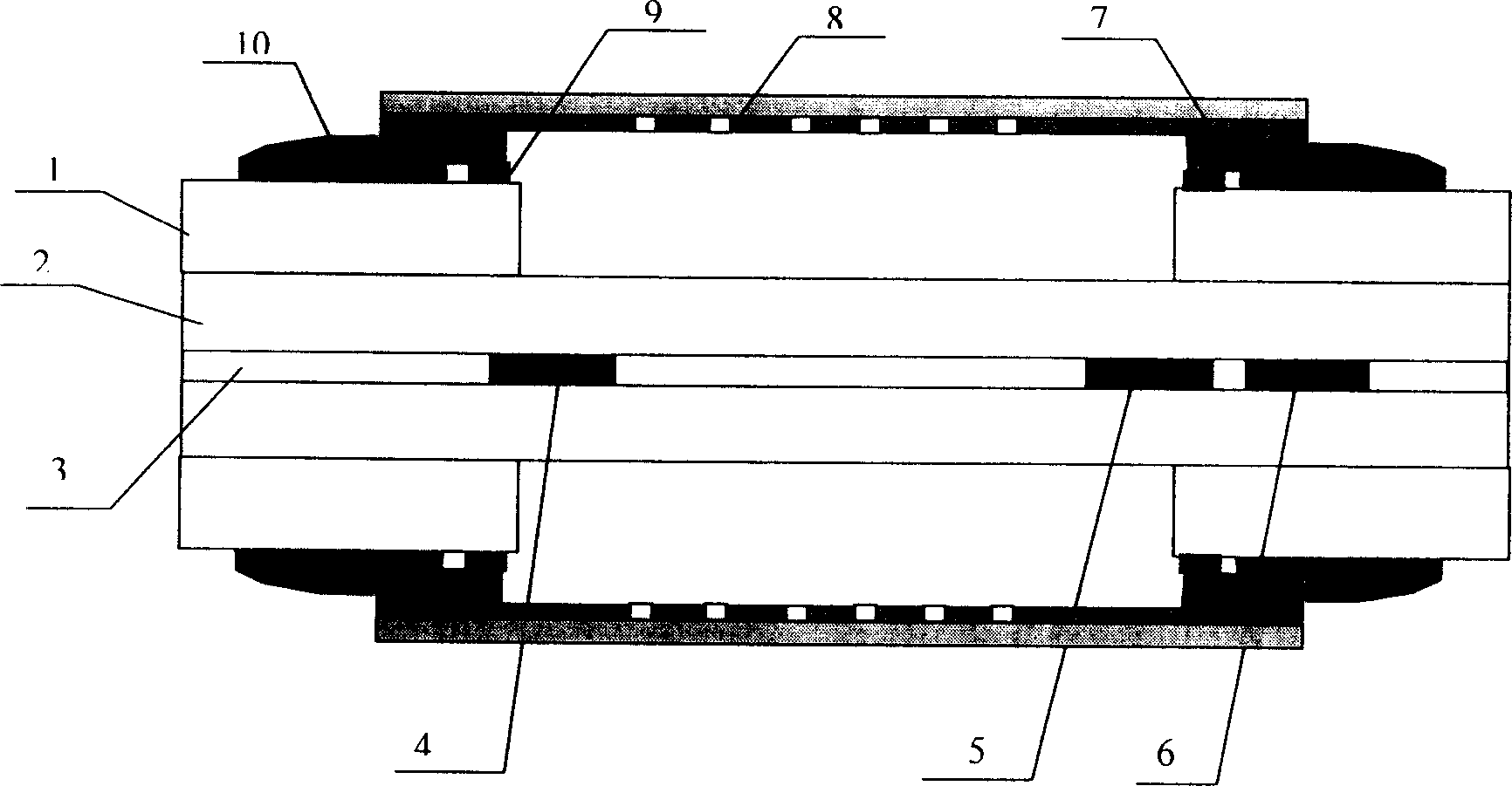
[0060] see figure 2 The structure of the SLR microstructure fiber gas sensor in this sensing system includes: fiber coating 1, fiber cladding 2, fiber core 3, long-period fiber grating LPFG14, long-period fiber grating LPFG25, short-period fiber grating 6 , protective cover 7, dust filter thin layer 8, curing glue 9, transition buffer cover 10. Among them, the optical fiber material is quartz, and two long-period fiber gratings with a length of about 20 mm are arranged on a section of optical fiber that has removed the plastic protective coating; the two long-period fiber gratings are 10 cm apart, and their coupling center wavelengths are both 1160 nm. Its 3dB bandwidth is 10nm, the coupling efficiency at the central wavelength is 99.7%, and the wavelength bandwidth at which the coupling efficiency is greater than 99% is 3.5nm; there is a short-period fiber grating outside the t...


PUM

PropertyMeasurementUnit
wavelengthaaaaaaaaaa

Abstract

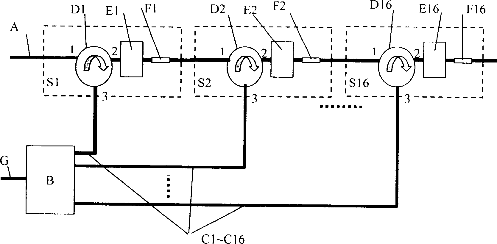
The invention discloses a distributed micro-structure optical fiber marsh gas sensing system and sensing method. The system is formed by a wind-band light source, a wide-band couple, an initial short period optical fiber grating, multiply series connecting single negative micro-structure optical fiber marsh gas sensors, an optical fiber link circuit, an optical fiber spectrum demodulator and a computer, wherein the single negative micro-structure optical fiber marsh gas sensor is formed by a short period optical fiber grating and two long period optical fiber gratings. The method is that it orientates the temperature factor and the sensing factor of each sensor; it then measures the marsh gas density of each sensing point.

Description

technical field [0001] The invention belongs to the technical fields of optical fiber sensing, gas chemistry and safety, and in particular relates to a distributed microstructure optical fiber gas sensing system and sensing method for obtaining gas concentration. Background technique [0002] In terms of mining safety, for a long time, major and extraordinarily large coal mine accidents have occurred frequently around the world, with hundreds of casualties. Every major accident brings huge property losses, especially irreparable losses to the lives of industrial workers, and poses a threat to families and society. One of the main causes of coal mine accidents is the explosion caused by high-concentration gas, and coal mine gas explosions often occur all over the world. At present, the effective monitoring and control of gas is still a worldwide problem. People have invested a lot of manpower and financial resources to study this problem, but with little success. Monitoring...

Claims


Application Information

Patent Timeline
Patent Type & Authority Applications(China)
IPC IPC(8): G01N21/31G01N21/01G06F19/00
Inventor 曾祥楷
Owner 重庆工学院
Learn More