Heat radiation assembly and its flow direction control structure

A technology for heat dissipation components and flow direction control, which is applied in the field of heat dissipation components and their flow direction control structures, and can solve the problems that heat energy cannot be dissipated well, the area of ​​the air outlet is reduced, and heat cannot be effectively dissipated.

Inactive Publication Date: 2006-05-03
DELTA ELECTRONICS INC
View PDF0 Cites 9 Cited by
  • Summary
  • Abstract
  • Description
  • Claims
  • Application Information

AI Technical Summary

Problems solved by technology

In this way, the heat source corresponding to the closed air outlet will not be effectively dissipated due to the lack of cooling effect of the fan, which seriously affects the stability of the overall electronic device operation.
At the same time, the overall air outlet area of ​​the heat dissipation component is also greatly reduced by this effect, so as to Figure 1D Take the fan assembly as an example. The original overall air outlet area includes air outlet 111 and air outlet 121. When the baffle plate 122 closes the air outlet 121, the overall air outlet area will...

Method used


Image

  • Heat radiation assembly and its flow direction control structure
  • Heat radiation assembly and its flow direction control structure
  • Heat radiation assembly and its flow direction control structure

Examples


no. 1 example

[0032] Please refer to Figure 2A and Figure 2B , which is a schematic diagram of the flow direction control structure according to the first embodiment of the present invention. For the sake of illustration, as Figure 2A As shown, the upper cover of the heat sink is removed to better understand the flow control structure. The flow direction control structure of this embodiment is used in a heat dissipation device 210, such as a blower fan (blower). The flow direction control structure includes several movable parts 23, which are arranged on the air outlet 211 of the heat dissipation device 210. Each movable part 23 has a fixed first end 231 and a corresponding movable second end 232 for use in To jointly guide the airflow direction.

[0033] The flow direction control structure is formed in a modular form, and is installed in any one or more appropriate positions of the heat sink 210 in a detachable manner. Each movable part 23 is rotatably arranged at the air outlet, ...

no. 2 example

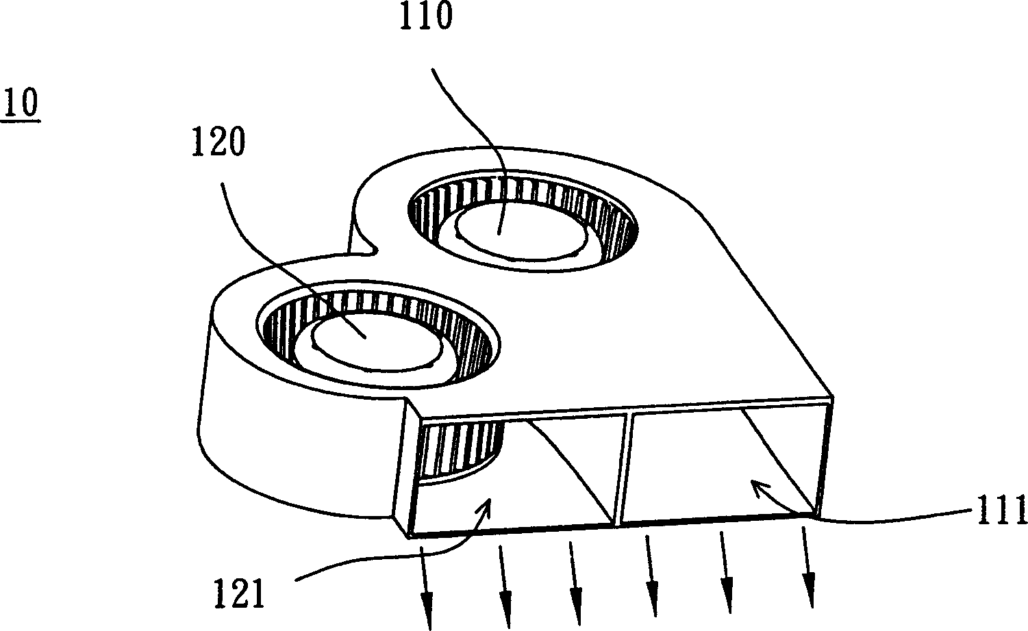
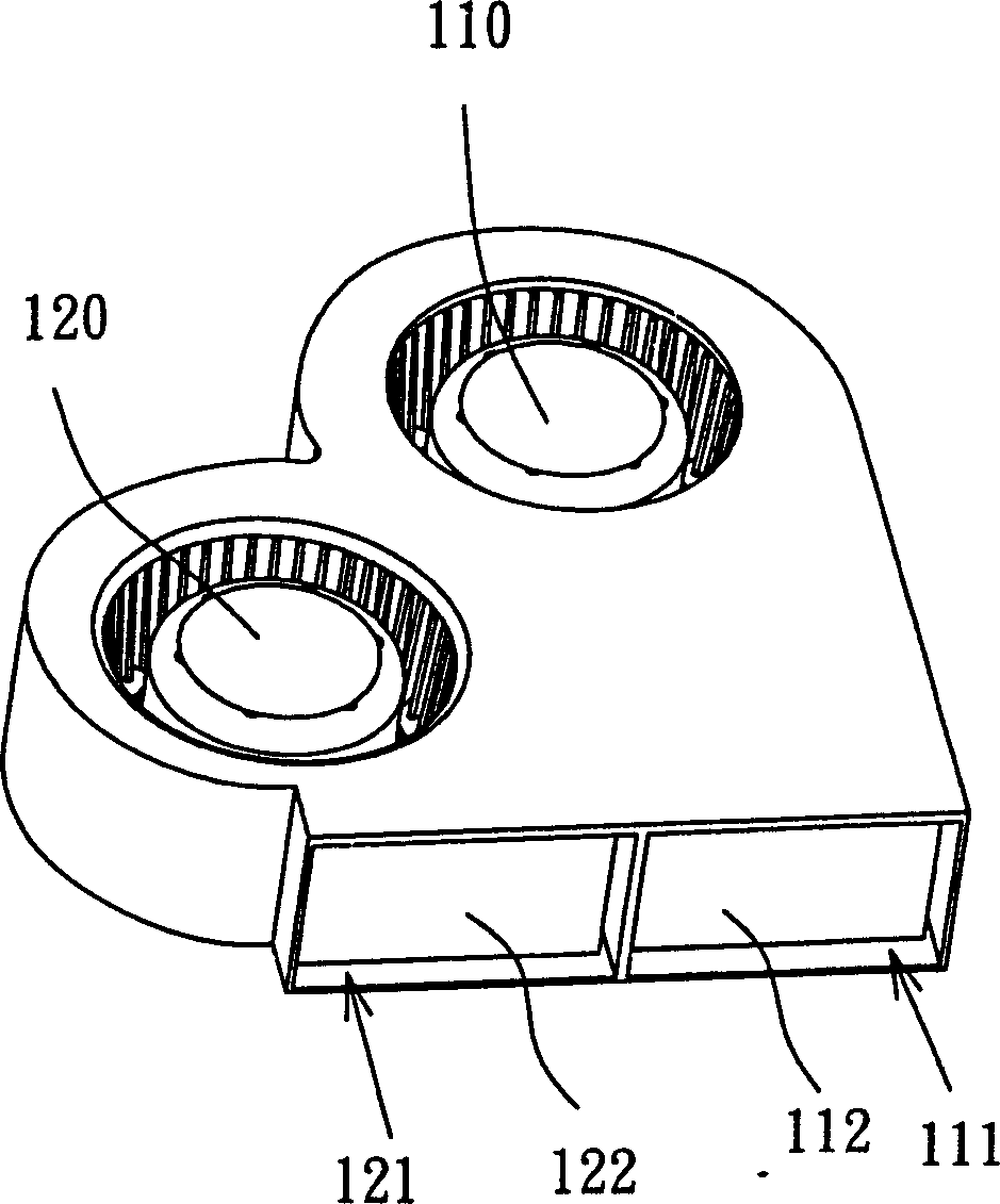
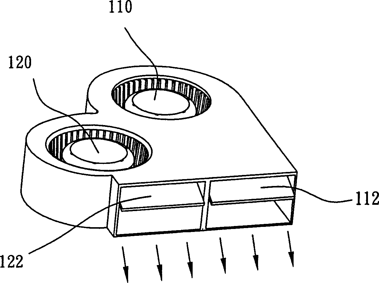
[0037] Please refer to Figure 3A and Figure 3B , Figure 3A is a schematic diagram of a heat dissipation assembly according to a second embodiment of the present invention, and Figure 3B yes Figure 3A Top view of the thermal assembly. The heat dissipation assembly 30 of this embodiment is, for example, a parallel fan, which at least includes a first heat dissipation device 310 , a second heat dissipation device 320 , and a flow direction control structure. The first heat dissipation device 310 and the second heat dissipation device 320 are arranged symmetrically, and an imaginary line passing through the connection point between the first heat dissipation device 310 and the second heat dissipation device 320 is taken as the criterion. The flow direction control structure includes several movable parts 33, which are arranged between the first heat sink 310 and the second heat sink 320, and an imaginary line passing through the connecting point between the first heat sin...

no. 3 example

[0045] Please refer to Figure 4A and Figure 4B , Figure 4A is a schematic diagram of a heat dissipation assembly according to a third embodiment of the present invention, and Figure 4B yes Figure 4A Top view of the thermal assembly. Similar to the second embodiment, the heat dissipation assembly 40 of this embodiment is, for example, a parallel fan, which at least includes a first heat dissipation device 410 , a second heat dissipation device 420 , and a flow direction control structure. The first heat dissipation device 410 and the second heat dissipation device 420 are arranged symmetrically, and an imaginary line passing through the connection point between the first heat dissipation device 410 and the second heat dissipation device 420 is taken as the criterion. The flow direction control structure includes a plurality of movable parts 43, which are arranged between the first heat sink 410 and the second heat sink 420, and an imaginary line passing through the con...


PUM


Abstract

The invention relates to a radiating component which at least comprises a first radiator, a second radiator and a flow direction controller. The first radiator and the second radiator are symmetry positioned; the flow direction controller structure comprises a plurality of movable units between the first radiator and the second radiator; each movable unit has a fixed first end and a corresponding movable second end used to separately lead the air flow direction of the first radiator and the second radiator. The bisect of the movable unit can be bar form, limb form, arc form or other non-linear forms; it has non-equal thickness or reducing thickness from the first end to the second end; each movable unit is overlap with the adjacent movable unit used to choosing seal the radiator.

Description

technical field [0001] The present invention relates to a cooling component and its flow direction control structure, and in particular to a cooling component with a low-noise flow control structure capable of controlling the flow direction of the airflow. Background technique [0002] With the continuous improvement of the performance of electronic devices, the heat sink has become one of the indispensable equipment in the current electronic devices, because if the heat energy generated by the electronic devices cannot be dissipated properly in real time, it will cause the performance of the electronic devices to deteriorate. It may cause burning of the electronic device. The heat dissipation device is even more important for microelectronic components (such as integrated circuits, integrated circuits), because with the increase of integration and the improvement of packaging technology, the area of ​​integrated circuits is continuously reduced, and the accumulated per unit...

Claims


Application Information

Patent Timeline
IPC IPC(8): H01L23/467G06F1/20H01L23/34H05K7/20
Inventor 邱永裕黄文喜
Owner DELTA ELECTRONICS INC
Why Eureka
Try Eureka