Quick forming method by adoption of projection technique

A projection technology and fast technology, applied in the field of manufacturing, can solve the problems of low degree of automation, high cost of use, poor molding accuracy, etc., and achieve the effect of large selection range, convenient control, easy control and adjustment

Inactive Publication Date: 2006-05-10
谭昊涯 +1
View PDF1 Cites 29 Cited by
  • Summary
  • Abstract
  • Description
  • Claims
  • Application Information

AI Technical Summary

Problems solved by technology

However, the resin in the sheet shrinks and concentrates during curing, resulting in poor molding accuracy. The more prominent problem is that this method needs to make a light leakage plat

Method used


Image

  • Quick forming method by adoption of projection technique
  • Quick forming method by adoption of projection technique
  • Quick forming method by adoption of projection technique

Examples


Embodiment 1

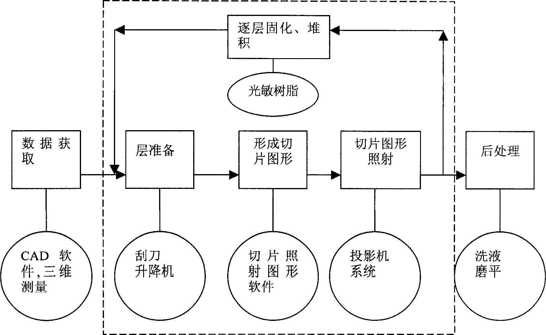
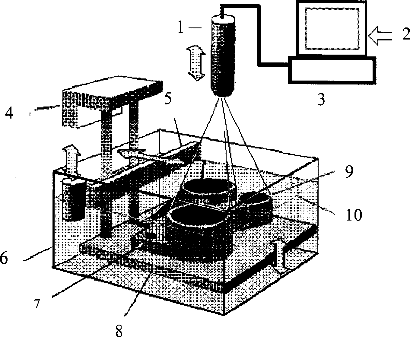
[0062] The structure of the rapid prototyping machine is as follows figure 2 As shown, load 50kg DuPont SOMOS 6100 photosensitive curing resin in liquid tank 6, load TGC-1 control software in computer 3 (TGC-1 control software flow process is as follows Figure 4 As shown), the digital three-dimensional model 2 of the object can be displayed on the computer monitor; the projector 1 connected to the computer is located above the tray 8, and the photosensitive resin on the tray is provided by the liquid tank 6, in order to keep the photosensitive resin liquid on the tray 6 The distance between the surface 10 and the projector is constant, so that the size of the projection graphics 9 on the photosensitive resin liquid surface remains the same, and the lifting of the tray 8 is adjusted by the lifter 4; a horizontally reciprocating scraper 5 is installed on the liquid tank 6 to ensure The stability of the liquid surface position of the thin layer photosensitive resin and the smoo...

Embodiment 2

[0082] The structure of the rapid prototyping machine and the rapid prototyping method are as in Example 1.

[0083] Projector parameters: Three-chip LCD transmission mode, resolution 800×600, light source 500W, iodine tungsten lamp, wavelength 40nm~800nm.

[0084] Control parameters: Irradiation area: 150mm×150mm

[0085] Forming shape: cube

[0086] Molding size: 100mm×100mm×100mm

[0087] Support size: 100mm×100mm×10mm

[0088] The thickness of each layer in the forming process of the molded object: 0.1mm

[0089] Irradiation times: support 50 times

[0090] The total number of irradiation times for forming entities: 10,000 times

[0091] Each irradiation time: 1.0 seconds

[0092] Test results: Molding time: 270 minutes (including the time required for the leveling action of the layer preparation and the switching of the irradiation pattern)

[0093] Physical size: 99.66mm×9.66mm×99.85mm...

Embodiment 3

[0099] The structure of the rapid prototyping machine and the rapid prototyping method are as in Example 1.

[0100] Projector parameters: Three-chip LCD reflection mode, resolution 1024×768, light source 50W, UHP lamp, wavelength 40nm~800nm.

[0101] Control parameters: Irradiation area: 120mm×120mm

[0102] Forming shape: cube

[0103] Molding size: 100mm×100mm×100mm

[0104] Support size: 100mm×100mm×10mm

[0105] The thickness of each layer in the forming process of the molded object: 0.1mm

[0106] Irradiation times: support 50 times

[0107] The total number of irradiation times for forming entities: 10,000 times

[0108] Each irradiation time: 1.0 seconds

[0109] Test results: Molding time: 386 minutes (including the time required for the leveling action of the layer preparation and the switching of the irradiation pattern)

[0110] Physical size: 99.66mm×9.66mm×99.85mm

[0111]Form...


PUM


Abstract

The invention belongs to the producing area, which uses modern shadow casting technique and computer image processing technique to process the illumination solidification modeling on the surface of liquid photosensitive resin to form the three-dimensional solid quickly. The invention processes the sectional mould data of three-dimensional solid via the computer fast shaping processing technique to generate the digital grid image data which can be directly used in projection, to be transformed into digital optical signal via the digital image projector, and adjusted by different time and space patterns to be irradiated over the surface of photosensitive resin to solidify it.

Description

technical field [0001] The invention belongs to the field of manufacturing, and particularly relates to a method for quickly forming a three-dimensional entity by light-curing molding on the surface of a liquid photosensitive resin by using modern projection technology and computer graphics processing technology. Background technique [0002] Rapid prototyping (RP for short) is a rapid and intelligent new prototyping method produced since the birth of computer control technology, which has set off a revolution in the manufacturing industry. A series of rapid prototyping methods have been developed around the use of computer control technology. Such as the technical scheme disclosed in US4575330, the SLS (Selective Laser Sintering) method developed by DTM Company of the United States, the FDM (Fused Deposition Mfg) method invented by Scott Crump engineers in the United States, the LOM (Laminated Object Mfg) method developed by companies such as Gropp in the United States, Jap...

Claims


Application Information

Patent Timeline
IPC IPC(8): B29C67/00G06F17/50
Inventor 谭昊涯曹瑞军谭东风童家仙
Owner 谭昊涯
Why Eureka
Try Eureka