
Desalination device of sea water

A water inlet pipe and water hole technology, which is applied in seawater treatment, general water supply saving, permeation/dialysis water/sewage treatment, etc., can solve the problems of high energy consumption and low efficiency, reduce energy consumption, improve diffusion speed, The effect of improving efficiency

Inactive Publication Date: 2006-05-10
HARBIN INST OF TECH
View PDF1 Cites 14 Cited by
  • Summary
  • Abstract
  • Description
  • Claims
  • Application Information

AI Technical Summary

Problems solved by technology

[0003] The purpose of the present invention is to provide a seawater desalinator to solve the defects of high energy consumption and low efficiency in seawater desalination in the prior art

Method used


Image

  • Desalination device of sea water
  • Desalination device of sea water

Examples


specific Embodiment approach 1

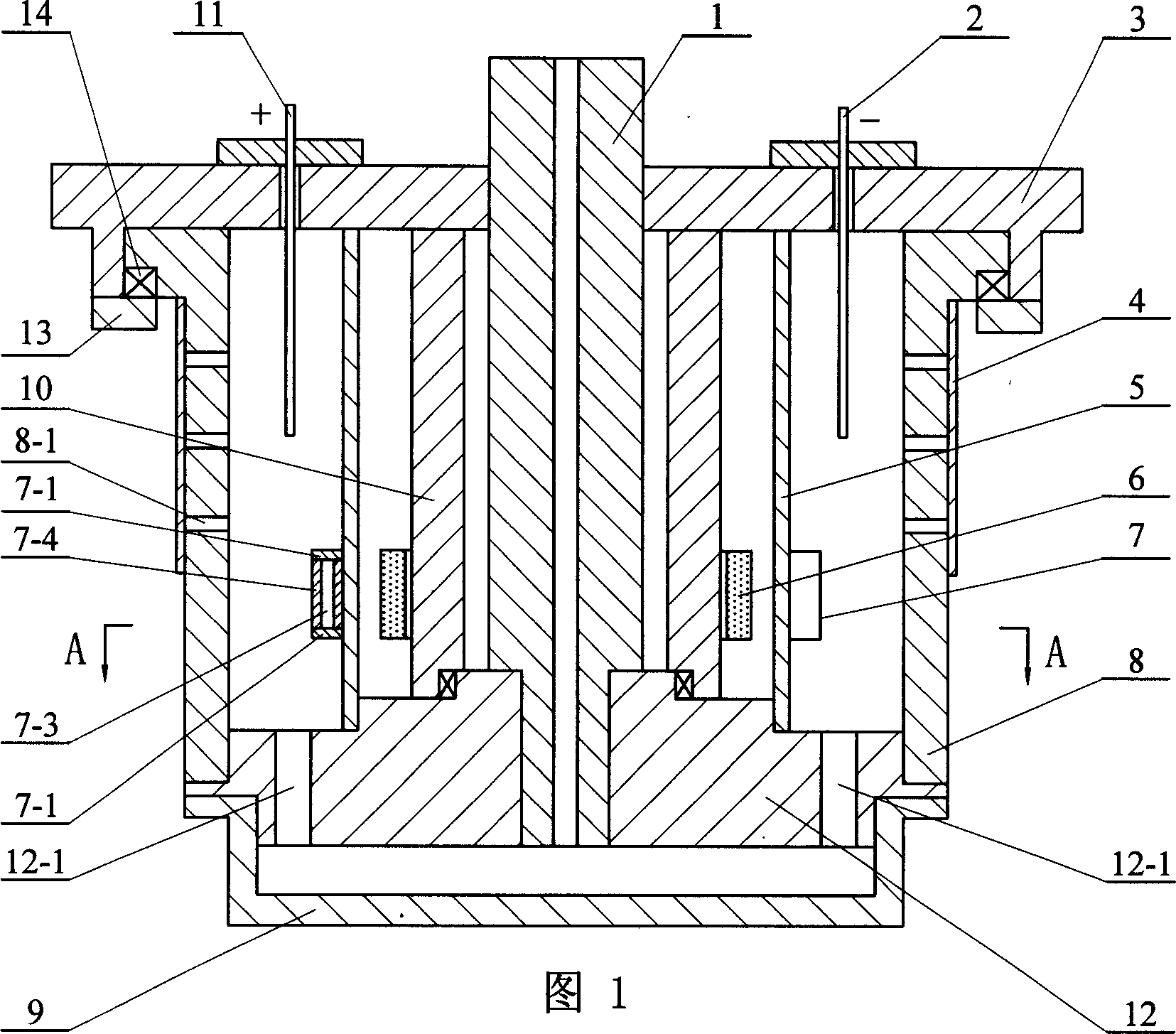
[0006] Specific Embodiment 1: The present embodiment will be specifically described below with reference to FIG. 1 . It consists of water inlet column 1, negative plate 2, positive plate 11, bottom plate 3, reverse osmosis membrane 4, rotor support sleeve 5, stator 6, rotor 7, rotating outer sleeve 8, sealing end cover 9, inner sleeve 10, separator 12 , retaining ring 13 and bearing 14, the upper end of the water inlet pipe column 1 passes through the bottom plate 3 and is fixed on the bottom plate 3, the inner sleeve 10 surrounds the outer circular surface of the water inlet pipe column 1, and one end of the inner sleeve 10 is fixed on the bottom plate 3 On the surface of the inner sleeve 10, the stator 6 is fixed on the outer surface of the inner sleeve 10, the rotor support sleeve 5 surrounds the outer surface of the stator 6, and the outer surface of the rotor support sleeve 5 corresponds to the position of the stator 6. Rotor 7, stator 6 and rotor 7 constitute the electro...

specific Embodiment approach 2

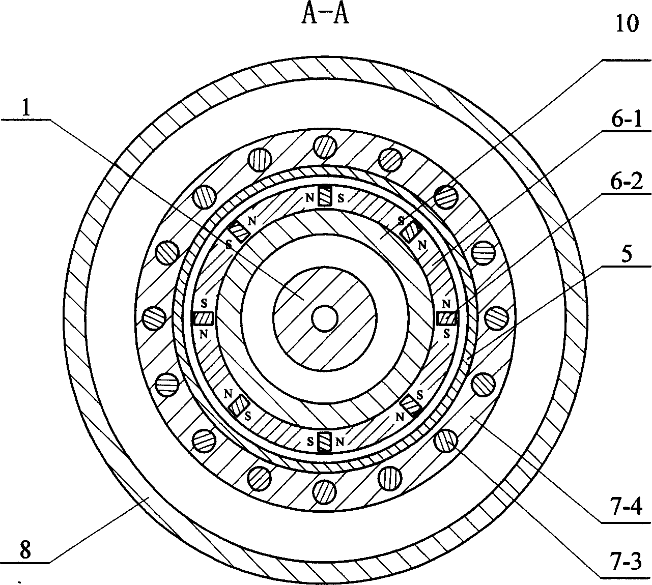
[0007] Specific embodiment two: below in conjunction with Fig. 1 and figure 2 This embodiment will be specifically described. The difference between this embodiment and Embodiment 1 is that the stator 6 is composed of a stator core 6-1 and several pieces of magnetic steel 6-2, the magnetic steel 6-2 is embedded in the stator core 6-1, and all the magnetic steel 6-1 2 uniformly arranged along the circumferential direction of the stator core 6-1, the magnetic steel 6-2 is magnetized along the tangential direction of the stator core 6-1, and the opposite surfaces of the adjacent magnetic steel 6-2 are filled with the same magnetic polarity. The magnetic steel 6-2 can also be magnetized along the radial direction of the stator core 6-1, as long as the magnetic field lines generated by the magnetic steel 6-2 can cut the rotating rotor. The rotor 7 is composed of a rotor core 7-4, several rotor copper strips 7-3 and two short-circuit rings 7-1. A short-circuit ring 7-1 is respectiv...


PUM


Abstract

The invention discloses a sea-water distillator combining high-temperature electrodialysis principle and film water treatment technique. It solves the drawback that, in the process of sea-water desalination, the energy-consumption is high and the efficiency is low with the prior art. The sea-water distillator comprises of an admitting pipe column 1, a negative plate 2, a positive plate 11, a bottom board 3, a reverse osmosis membrane 4, a rotor supporting jacket 5, a stator 6, a rotor 7, a rotating jacket 8, a sealed end cap 9, an inner sleeve 10, a baffle 12, a stud 13 and a bearing 14, the upper edge of 1 being through and fixed on 3, 6 and 7 making up an electromagnetic heater, the cave of 1 connecting with the water-passing hole of 8 by the feed-through of baffle, 4 covering on the cylindrical surface of 8 and retaining the water-passing hole, 2 and 11 being through 3 and provided between the inner hole of 8 and the excircle of 5. Sea-water flows into 1 and enters between 5 and 8, 2 and 11 can decrease the viscosity and improve the diffusion velocity of sea-water and increase the conductance between sea-water and 4, and it can generate centrifugal force and provide hyperfiltration pressure for the film when 8 rotates with a high speed.

Description

technical field [0001] The invention relates to a seawater desalination device, in particular to a seawater desalination device which combines the principle of high-temperature electrodialysis and membrane water treatment technology. Background technique [0002] One of the biggest problems facing the world in the 21st century is the water crisis. Although the total amount of water resources in my country is relatively large, the distribution is uneven, and the per capita water resources are low. Some cities are often threatened by water shortages and water shortages. Therefore, the development of new water sources and the control of water pollution have become a hot topic of concern. Among them, seawater desalination is an important way to obtain water for human life and production. Currently, seawater desalination methods mainly include membrane separation, electrodialysis, and distillation. Among them, the distillation method consumes the most energy, followed by the e...

Claims


Application Information

Patent Timeline
IPC IPC(8): C02F1/44C02F1/469C02F103/08
CPCY02A20/124Y02A20/131
Inventor 郭斌程树康杨世彦刘小芳谢大钢裴宇龙宫海龙
Owner HARBIN INST OF TECH
Learn More