Co-rail oil injection system electric control oil injector

A technology of electronically controlled fuel injection and fuel injection system, which is applied in the direction of charging system, machine/engine, fuel injection device, etc., and can solve the problem of inability to select the flow coefficient of the orifice, difficulty in controlling the tolerance of the gap A, and affecting the fuel injector. Performance and other issues, to achieve the effect of improving dynamic response characteristics, reducing the difficulty of manufacturing process, and reducing quality

Inactive Publication Date: 2006-05-17
WUXI OIL PUMP NOZZLE INST
View PDF4 Cites 22 Cited by
  • Summary
  • Abstract
  • Description
  • Claims
  • Application Information

AI Technical Summary

Problems solved by technology

Therefore, the precision requirements of the valve body (14) are very high, the manufacturing process is very difficult, and it is impossible to select and match according to the measured orifice flow coefficient
In addition, the working clearance A of the armature (9) is affected by th

Method used


Image

  • Co-rail oil injection system electric control oil injector
  • Co-rail oil injection system electric control oil injector
  • Co-rail oil injection system electric control oil injector

Examples


Example Embodiment

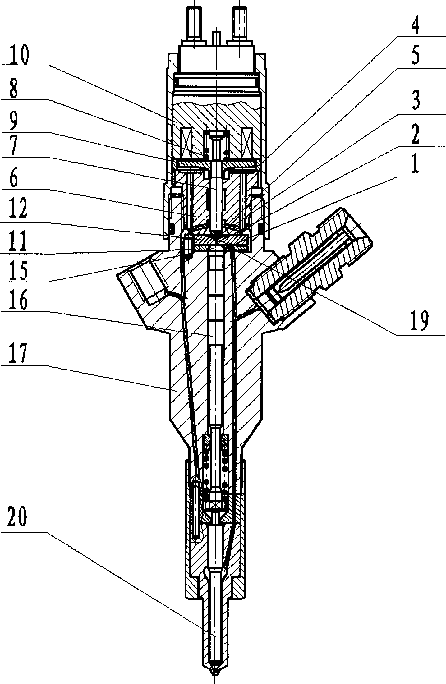
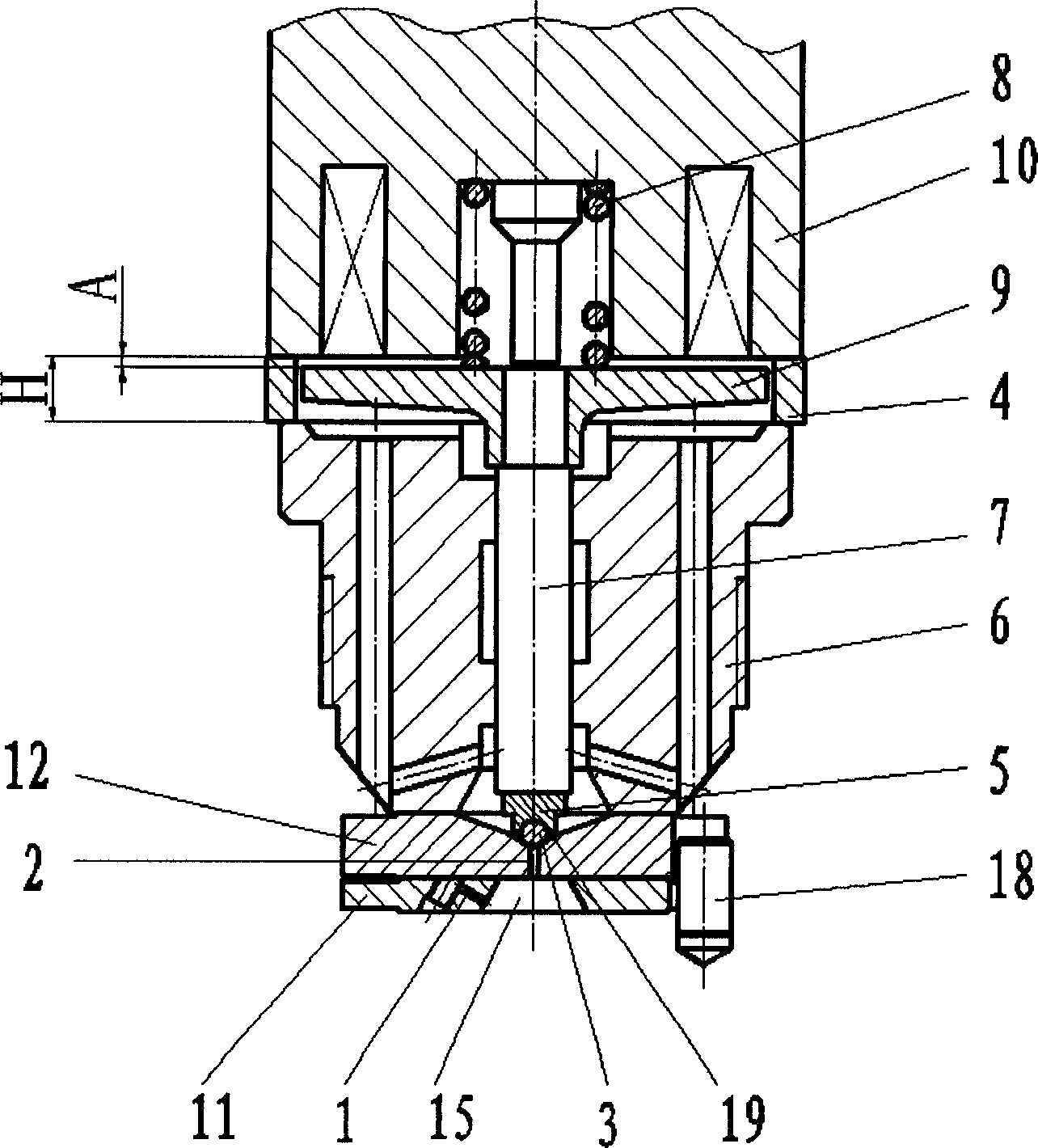
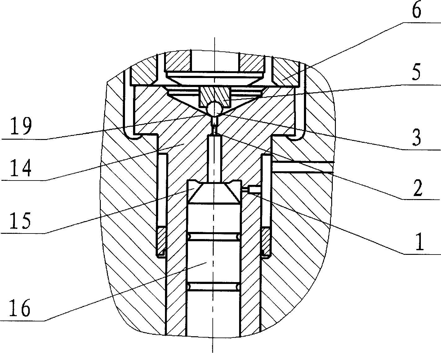
[0009] figure 1 It is a cross-sectional view of an electronically controlled fuel injector of a common rail fuel injection system that adopts the technical solution of the present invention. figure 2 It is an enlarged view of the control valve part, which includes parts and structural elements: electromagnet parts (10), armature (9), spring (8), armature rod (7), control valve seat (6), ball Seat (5), adjusting ring (4), valve ball (3), orifice positioning pin (18), and orifice plate (11) processed with oil inlet orifice (1), and processed with oil return The orifice (2) and the large orifice plate (12) of the sealing cone (19). The pressure control chamber (15) is located at the middle hole of the throttle orifice plate (11). The orifice plate positioning pin (18) is used to fix the circumferential position of the orifice plate (11 and 12). The large throttling orifice plate (12) is installed between the small throttling orifice plate (11) and the control valve seat (6), and t...


PUM

PropertyMeasurementUnit
Diameteraaaaaaaaaa

Abstract

The present invention relates to an electronic-controlled fuel injector of diesel engine common-rail injection system. Its control valve portion structure is characterized by that it has a throttle small orifice plate with fuel inlet orifice, a throttle large orifice plate with fuel-returning orifice and sealed cone and a regulating ring capable of regulating working gap of armature iron.

Description

Technical field [0001] The invention belongs to an electronic control injector of an internal combustion engine common rail fuel injection system, and particularly relates to the structural design improvement of the control valve part of the electronic control fuel injector of the common rail fuel injection system of a compression ignition engine (diesel engine). Background technique [0002] The structure of the control valve part of the existing electronic control injector suitable for the common rail injection system of the diesel engine is shown in the drawings of the disclosed CN1397727A (JP2003028021) and CN1469039A (JP2004019551) patents ( image 3 ), is a typical injector control valve. When the electromagnet (10) is energized, the armature (9) overcomes the pressure rise of the spring (8) under the action of the suction current. At this time, the valve ball (3) and the valve seat (5) The armature rod (7) is lifted up together, and at the same time the increased suction c...

Claims


Application Information

Patent Timeline
IPC IPC(8): F02M51/06F02M61/04
Inventor 庄福如胡林峰蒋鹤
Owner WUXI OIL PUMP NOZZLE INST
Why Eureka
Try Eureka