Reinforced concrete hollow slab

A technology for reinforced concrete and hollow slabs, which is applied in the field of reinforced concrete hollow slabs, and can solve the problems of inconvenient construction, high damage rate, and high construction cost of reinforced concrete hollow slabs

Inactive Publication Date: 2006-05-24
湖南邱则有专利战略策划有限公司
View PDF3 Cites 0 Cited by
  • Summary
  • Abstract
  • Description
  • Claims
  • Application Information

AI Technical Summary

Problems solved by technology

However, this kind of reinforced concrete hollow slab, because the cavity components used in it are easy to break during the process of handling and construction, the structura

Method used


Image

  • Reinforced concrete hollow slab
  • Reinforced concrete hollow slab
  • Reinforced concrete hollow slab

Examples


Embodiment Construction

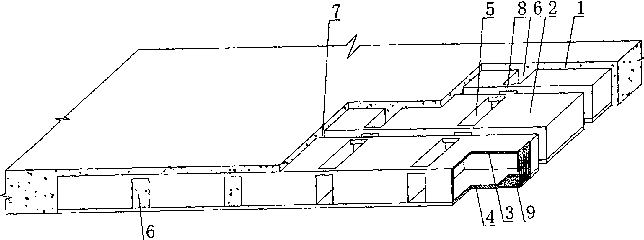
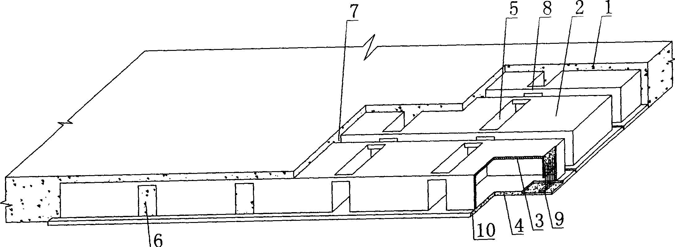
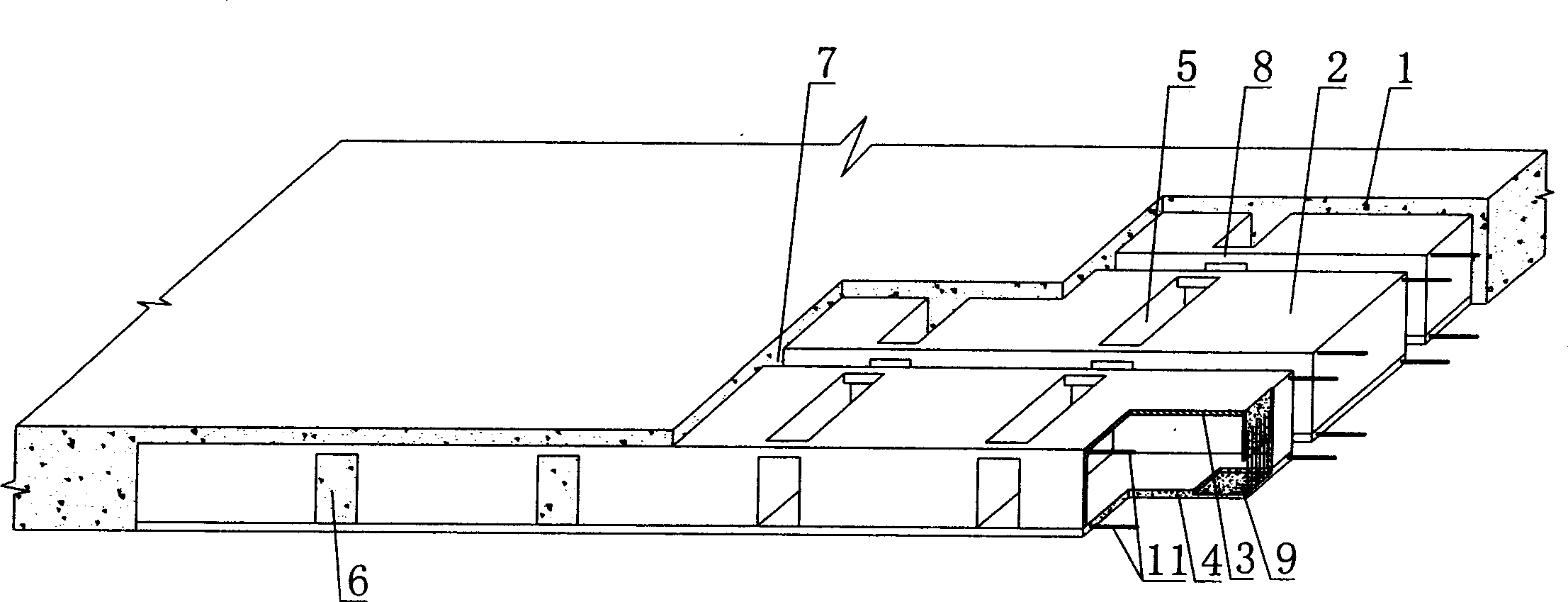
[0061] The present invention will be further described below in conjunction with the accompanying drawings and embodiments.

[0062] As shown in the accompanying drawings, the present invention includes reinforced concrete 1, a cavity member 2, the cavity member 2 is contained in the reinforced concrete 1, the cavity member 2 includes a cavity formwork 3, a structural bottom plate 4, and the cavity formwork 3 It is connected with the structural bottom plate 4 as a whole, and there are at least two or more cavity formworks 3 arranged alternately on the structural bottom plate 4, and the interphase cavities between the cavity formworks 3 and the structural bottom plate 4 form the cast-in-place structural inner rib cavity 5, The cast-in-place reinforced concrete hidden ribs 6 are formed in the inner rib mold cavity 5, and a plurality of cavity members 2 are arranged alternately with each other. 6 together form a structural system where the main and hidden ribs intersect, which is...


PUM


Abstract

A reinforced steel concrete hollow plate includes reinforced steel concrete, hollow member having hollow form shell, structure bottom plate, inner rib form cavity, site casting reinforced steel concrete forming site casting reinforced steel concrete built in rib, support-draw piece connected with adjacent hollow form cavity which are arranged in same longitudinal axis, said hollow form shell is fabricated opened basin shape form shell, at least two basin shape form shell are integrated snapped on reinforced steel concrete base plate, and having anchor piece anchored on structure base plate. Said invention adapts for hollow plate of reinforced steel concrete, building cover, and bridge.

Description

(1) Technical field [0001] The invention relates to a reinforced concrete hollow slab. (2) Background technology [0002] At present, most of the buildings with brick-concrete structure and reinforced concrete structure use prefabricated hollow slabs as floor slabs. This floor slab has the advantages of fast construction speed and low cost. However, because there is no firm connection between two adjacent prefabricated hollow slabs, only cement mortar is used to fill the joints, so the integrity is poor, which is not conducive to earthquake resistance, and cracks and water seepage often occur in the gaps. In order to solve the above problems, many buildings adopt the method of cast-in-place concrete floor slabs (solid and hollow). Although the problems of earthquake resistance and cracking have been solved, a large number of templates are used during construction, which not only increases the cost, but also slows down the construction speed and prolongs the construction peri...

Claims


Application Information

Patent Timeline
IPC IPC(8): E04B5/36E04C5/01E04G15/06
Inventor 邱则有
Owner 湖南邱则有专利战略策划有限公司
Why Eureka
Try Eureka