Method for machining clutch shafts

The technology of a clutch shaft and processing method, which is applied in the processing field of the fourth-speed clutch shaft, can solve the problems of high raw material requirements, low yield rate, complex production process, etc., and achieve the effects of simple processing technology, long product life and simple process steps

Inactive Publication Date: 2006-05-31
SHANGHAI JIAOYUN AUTOMOTIVE POWER SYST
View PDF0 Cites 4 Cited by
  • Summary
  • Abstract
  • Description
  • Claims
  • Application Information

AI Technical Summary

Problems solved by technology

[0004] The technical problem to be solved by the present invention is to provide a processing method for the shaft of the fourth-gear clutch, so as to overcome the shortcomings of the existing fourth-gear clutch shaft, such as high raw material requirements, complex production process, and low yield.

Method used


Image

  • Method for machining clutch shafts
  • Method for machining clutch shafts
  • Method for machining clutch shafts

Examples


specific Embodiment approach

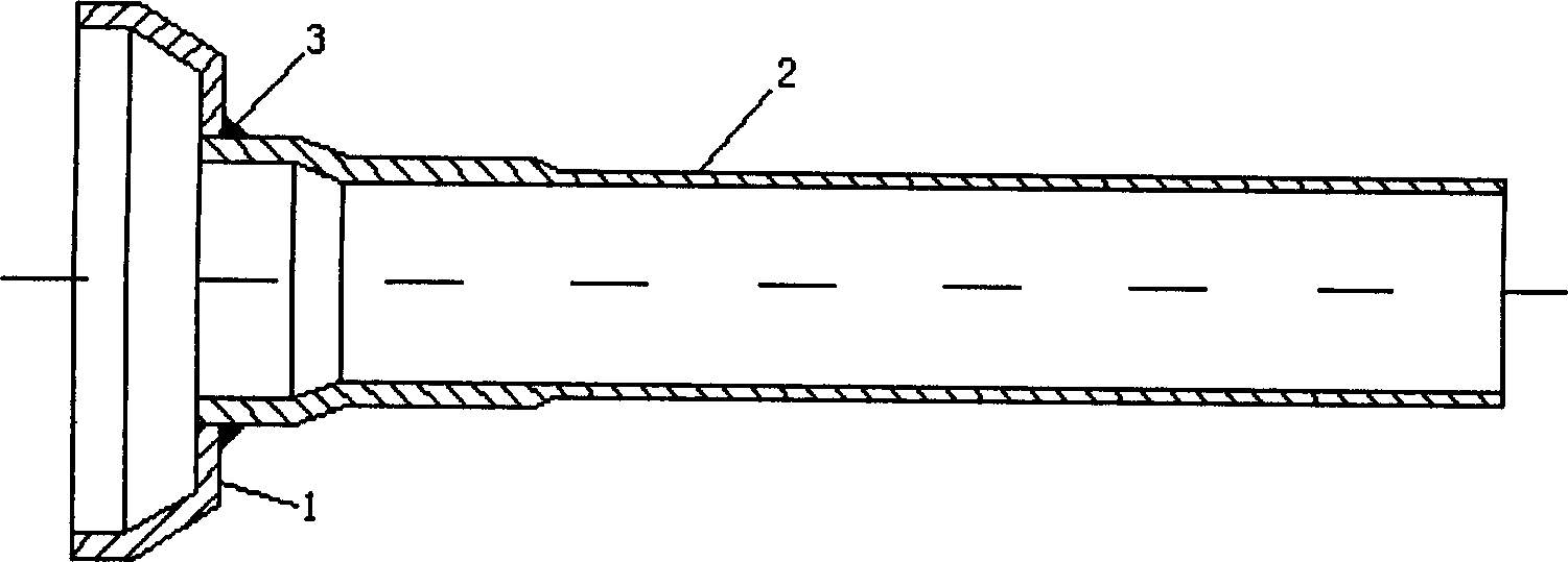
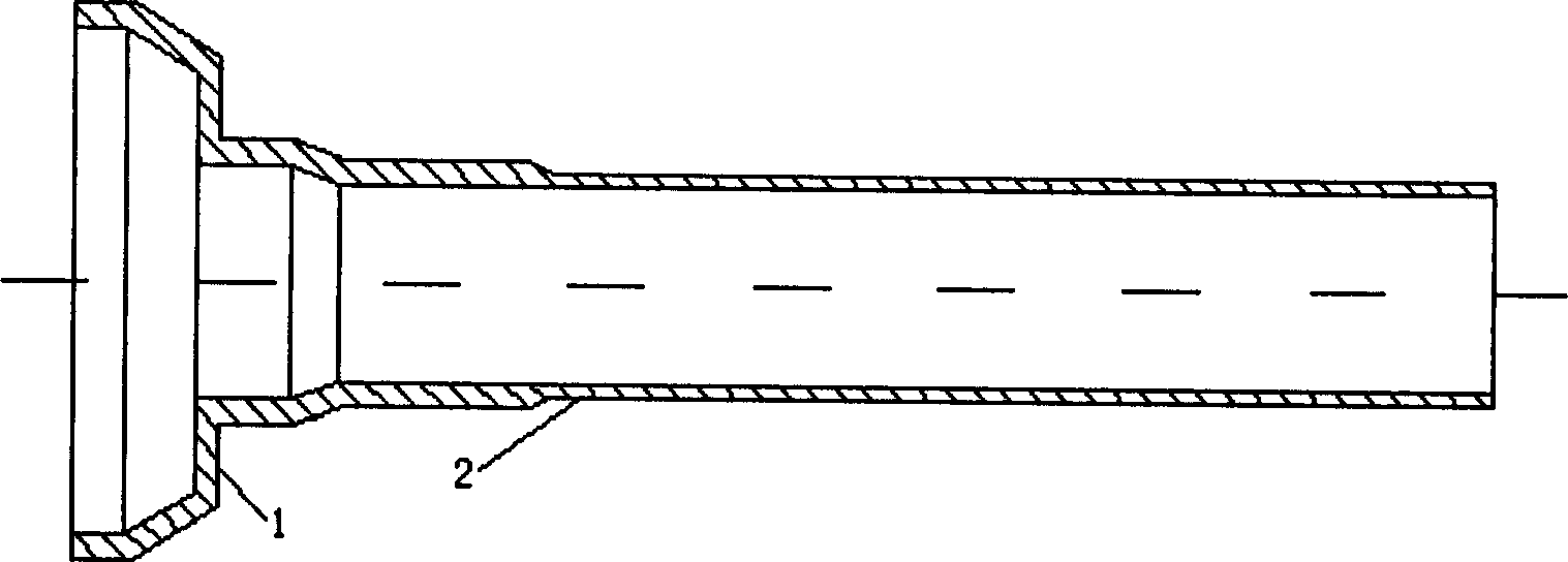
[0021] see figure 1 , it can be seen that the traditional clutch shaft includes a hub 1 and a shaft 2, and the joint part 3 between the hub 1 and the shaft 2 is connected by laser welding. see figure 2 , the clutch shaft obtained by the method of the present invention includes a hub 1 and a shaft 2, the hub and the shaft are an integral component and seamlessly connected.

[0022] see figure 2 , image 3 , Figure 4 with Figure 5 , the processing method of clutch shaft of the present invention comprises the steps:

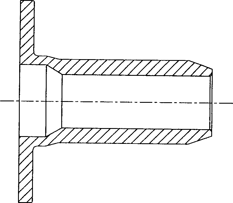
[0023] a) will image 3 The shown blank is forged into a "T"-shaped short shaft; it is made of domestic material blanks through forging, drilling, heat treatment, and turning. The pressure during forging is 800 tons, and the drilling diameter is φ26.5±0.3. The hardness is HRB60-74.

[0024] b) Wheel hub forming: use cold spinning process to directly cold spin the head of the "T" shaped shaft into a hub; use CNC automatic 3-spinning roller precision spinn...


PUM


Abstract

A technology for manufacturing the axle of clutch includes such steps as forging to form a T-shaped short axle, cold spinning on one end of said T-shaped axle to form a hub, and cold spinning of the axle to become a hollow long axle with the aperture ratio of 4-8.

Description

technical field [0001] The invention relates to a method for processing a clutch shaft, in particular to a method for processing a fourth-speed clutch shaft in an automobile gearbox. Background technique [0002] The hub and shaft of the 4th gear clutch shaft commonly used at present are split type, that is, the hub and the shaft are processed separately, the hub and the shaft are press-fitted, and then formed by laser welding. Using this traditional method to produce clutch shafts requires very high material requirements, because the raw materials for the hub and shaft must be imported from abroad, and there are disadvantages such as high purchase price and high risk in terms of raw materials. Moreover, the wheel hub processing technology is made of steel plate stamped and stretched and then spline broached, which has a long process; the shaft technology is made of steel plate rolled into a tubular shape, welded and cold extruded into a hollow slender shaft, the process is ...

Claims


Application Information

Patent Timeline
Patent Type & Authority Applications(China)
IPC IPC(8): B23P13/00B21D22/14
Inventor 刘昌华孙新毅
Owner SHANGHAI JIAOYUN AUTOMOTIVE POWER SYST
Why Eureka
Try Eureka