Laser position judging system and method

A laser position and laser technology, which is applied in the field of laser detection systems, can solve the problems of large volume of laser sensing systems, unsuitable for popularization and inconvenience in use, etc., and achieves the effect of simple judgment process, easy implementation, and simple processing circuit.

Inactive Publication Date: 2006-06-07
ASIA OPTICAL CO INC
View PDF1 Cites 7 Cited by
  • Summary
  • Abstract
  • Description
  • Claims
  • Application Information

AI Technical Summary

Problems solved by technology

Although this method can accurately determine the position of high-power lasers, it uses a large number of sophisticated optical components an

Method used


Image

  • Laser position judging system and method
  • Laser position judging system and method
  • Laser position judging system and method

Examples


Embodiment Construction

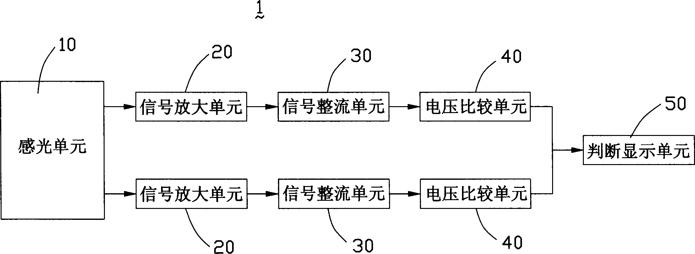
[0014] Please refer to figure 1 As shown, the laser position judgment system 1 of the present invention mainly includes a photosensitive unit 10 , two signal amplification units 20 , two signal rectification units 30 , two voltage comparison units 40 and a judgment display unit 50 .

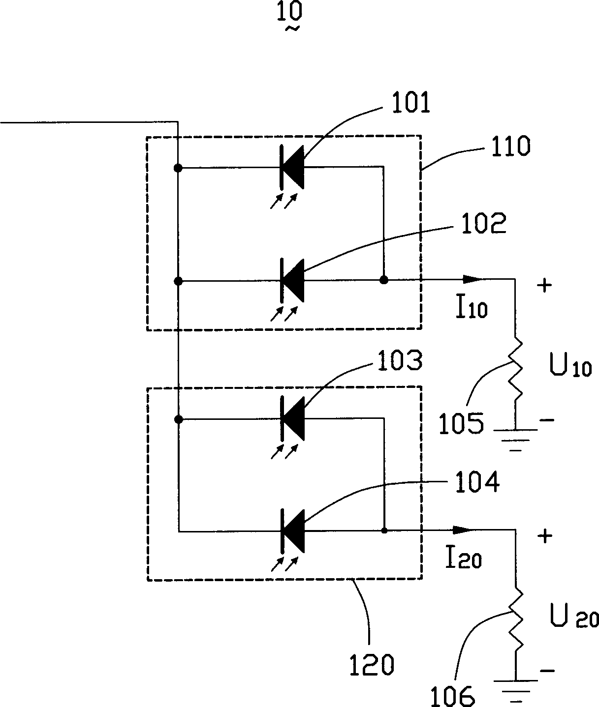
[0015] Please refer to figure 2 with Figure 5 As shown, the photosensitive unit 10 is used to sense the laser light emitted by the laser emitting device (not shown), which mainly includes four parallel and closely arranged photodiodes 101, 102, 103 and 104, wherein two photodiodes 101 and 102 is connected in parallel as the first photoreceptor 110 , and the other two photodiodes 103 and 104 are connected in parallel as the second photoreceptor 120 . The light-receiving surface of the first photoreceptor 110 is used to receive irradiation from a laser source (not shown), thereby receiving laser light, and is electrically connected to the first resistor 105 . The light-receiving surface of the...


PUM


Abstract

The present invention provides a kind of laser position judging system and method for judging laser irradiation position. The system includes a photosensitive unit with photodiode to convert received laser beam into electric signal; a signal amplifier unit to amplify electric signal; a signal rectifying unit to convert the rectified signal into positive output signal; a voltage comparison unit with one input end connected to the output of the signal rectifying unit and one other reference voltage input end; and a judging response unit including a responder to the output signal of the voltage comparison unit. When the output signal of the voltage comparison unit is high level, the responder responses to represent sensed laser and two sensing points are found out successively to find the connection line as the horizontal laser position. The present invention completes laser position judgment with photodiodes and simple circuit, and is simple, feasible, low in cost and high in precision.

Description

【Technical field】 [0001] The invention relates to a laser detection system, in particular to a system and method for judging the irradiation position of laser light emitted by a laser emitting device. 【Background technique】 [0002] In engineering fields such as construction, assembly positioning calibration, and mechanical machine tool track calibration, it is usually necessary to use lasers to make horizontal lines, vertical lines or correct horizontal planes. According to its specific use, laser is often used in two optical devices, laser level and laser rangefinder. The above two optical devices are equipped with a laser emitting device. Whether it is to detect the position of the laser emitted by the laser level or to measure the detection distance of the laser rangefinder, in practical applications, the laser is emitted by the laser emitting device. And through artificial or optical equipment to judge the irradiation position of the laser. For the judgment of the pos...

Claims


Application Information

Patent Timeline
IPC IPC(8): G01C15/00
Inventor 简张勇
Owner ASIA OPTICAL CO INC
Why Eureka
Try Eureka