Motor controller and steering device

A technology of motor controller and motor, which is applied in the direction of controlling electromechanical brakes, control systems, steering mechanisms, etc., and can solve problems such as driver discomfort

Inactive Publication Date: 2006-06-07
DENSO CORP
View PDF2 Cites 5 Cited by
  • Summary
  • Abstract
  • Description
  • Claims
  • Application Information

AI Technical Summary

Problems solved by technology

[0005] Furthermore, when the motor disclosed in Patent Document 2 is driven by using the above-mentioned motor controller, torque variation occurs in

Method used


Image

  • Motor controller and steering device
  • Motor controller and steering device
  • Motor controller and steering device

Examples


no. 1 example

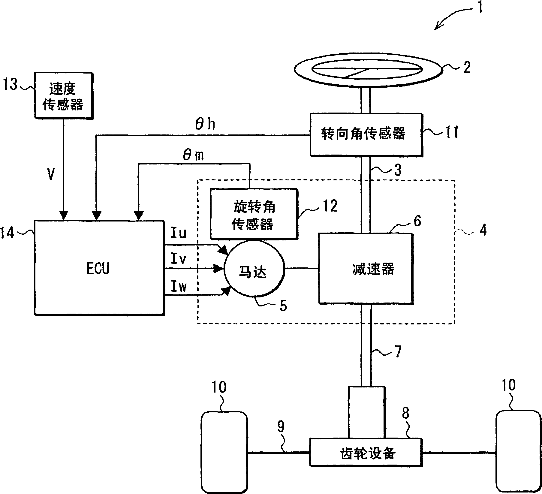
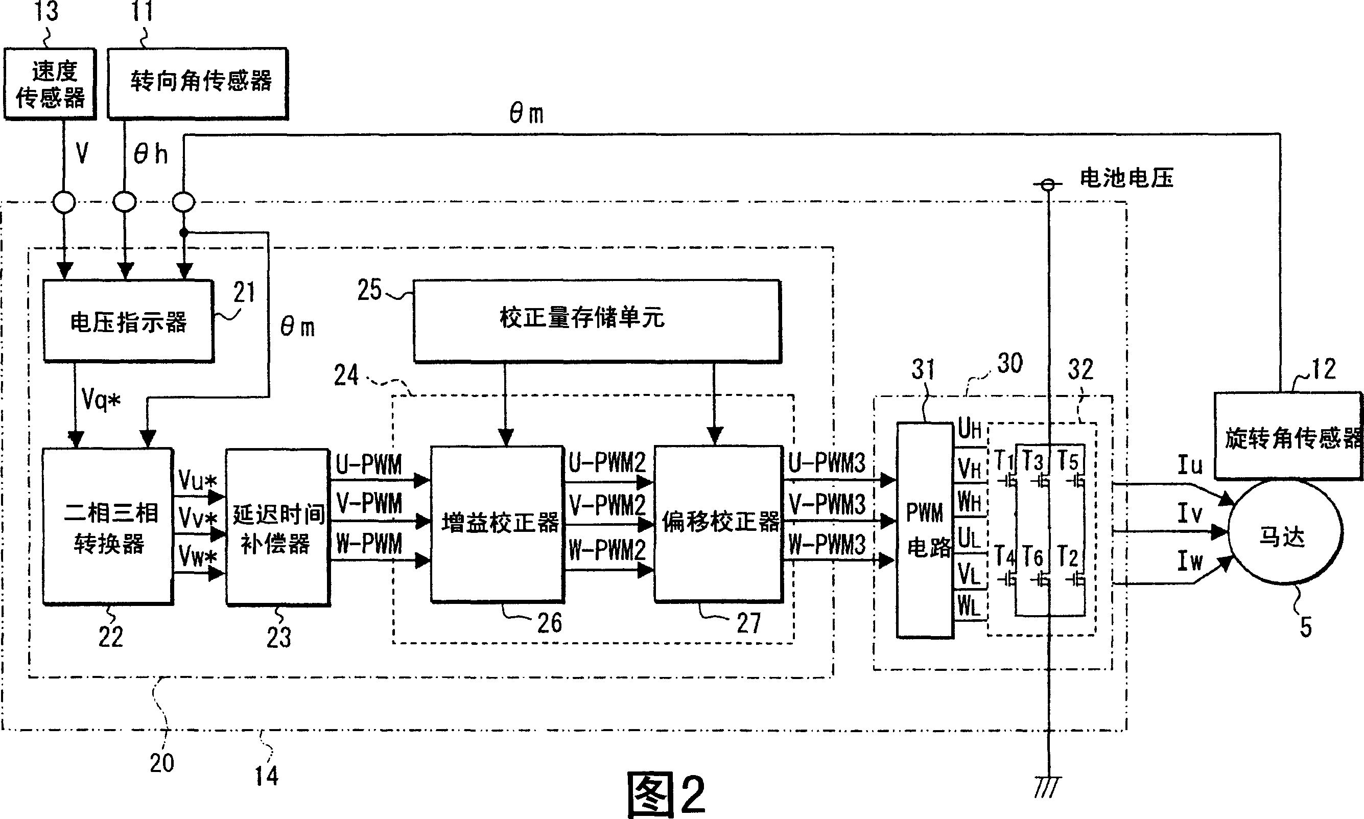
[0045] The first embodiment will be described with reference to the drawings. figure 1 It is a block diagram showing the structure of the steering equipment. FIG. 2 is a block diagram showing the structure of a motor controller for an electric motor (referred to as a motor) applied to a steering apparatus. In this embodiment, a steering device having a transmission ratio changing mechanism will be described as a steering device for changing the rotation transmission ratio between the steering angle of the steering wheel and the rotation angle of the steering wheel in accordance with the vehicle speed. For example, the rotation transmission ratio of the transmission ratio changing mechanism is controlled by the steering device so that when the vehicle is stopped or moving at a low speed, the turning angle of the steering wheel is greater than the steering angle of the steering wheel, thereby reducing the amount of operation of the steering wheel by the driver. On the other hand, w...

no. 2 example

[0113] The second embodiment will be described. In this embodiment, the inverter 30 is constructed by MOSFETs (T1, T2, T3, T4, T5, T6) having electrical characteristic values ​​within a predetermined range.

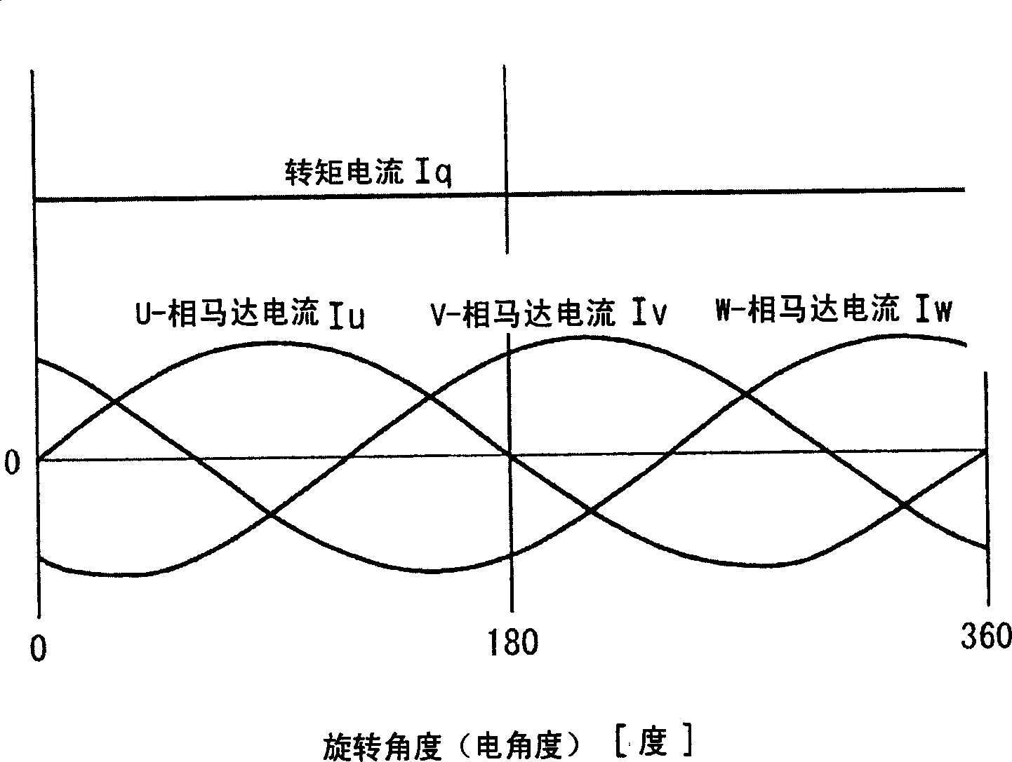
[0114] MOSFETs (T1, T2, T3, T4, T5, T6) are divided into a plurality of groups, in which the range of the threshold voltage Vth of the MOSFET or the range of the parasitic capacitance C of the MOSFET is different, and the converter 30 consists of the same group MOSFET (T1, T2, T3, T4, T5, T6) is constructed. Therefore, the deviation of the electrical characteristic values ​​of the MOSFETs (T1, T2, T3, T4, T5, T6) constituting the inverter 30 can be suppressed, and the waveforms of the respective phases generated by the inverter 30 can be made consistent with each other, so that the rotation can be suppressed. The surge of the moment current Iq and the torque change of the motor 5 can be suppressed.

[0115] It is not necessary to perform grouping of MOSFETs (T1, T2, T3, T4, T...


PUM


Abstract

A correction unit calculates a correction amount so that sine waves of the respective phases are coincident with one another and changes a PWM signal for carrying out the PWM control on switching elements e.g. metal oxide semiconductor field effect transistors (MOSFETs) based on the computed correction amount. A storage unit is adapted to store the correction amount for each phase based on the detection result. The switching elements are subjected to pulse width modulation (PWM) control to generate sine waves of multiple phases. A motor (5) includes a stator coil that produces rotational magnetic field upon receiving sine waves, and a rotor that is driven by the action of the rotational magnetic field.

Description

Technical field [0001] The technical field generally relates to a motor controller for control driven by an inverter, and a steering apparatus. Background technique [0002] JP-A-2002-10685 (Patent Document 1) discloses a related art time compensation control for a motor driven by an inverter. The motor control device of this publication provides a compensation amount for the delay time due to the PWM control to the PWM signal for driving the inverter. According to this motor control device, the delay time compensation gain is calculated in accordance with the torque amount calculated based on the torque current command value, whereby the calculated compensation gain is multiplied by the compensation amount described above to correct the PWM signal. Therefore, the PWM signal to be transmitted to the inverter can be smoothed, so that the current change of the motor can be suppressed, and the torque change of the motor can be suppressed. [0003] In addition to the above-mentioned ...

Claims


Application Information

Patent Timeline
IPC IPC(8): H02P27/06H02P21/00H02P21/05H02P23/04H02P25/022H02P25/03H02P27/08
CPCB62D5/046H02P6/10H02P21/05H02P27/08H02P27/085
Inventor 日高研一郎平峰干大河合元史筒井敏雄宫田正浩小城隆博
Owner DENSO CORP
Why Eureka
Try Eureka