
Buried line locator with integral position sensing

A locator and circuit technology, applied in the field of electronics, can solve problems such as the time length is not allowed, the tape measure cannot provide accuracy, and the measurement cannot be performed in real time, so as to achieve the effect of precise physical position

Inactive Publication Date: 2006-06-07
VIVAX METROTECH
View PDF3 Cites 14 Cited by
  • Summary
  • Abstract
  • Description
  • Claims
  • Application Information

AI Technical Summary

Problems solved by technology

The problem with using GPS for this purpose is that the accuracy of GPS and even differential GPS (DGPS) is often not sufficient
Although some GPS embodiments provide an accuracy of less than 1 inch, these measurements cannot be made in real time because the locator's receiver moves spatially at a reasonable rate within the area of ​​interest
[0009] Another problem in the area of ​​locating underground lines is the need to keep track of the location of buried lines over periods of time lasting hours or days
The tape measure used in this method does not provide the required level of accuracy
In addition, the length of time required to obtain accurate position data for line locator measurements using a tape measure is often intolerable

Method used


Image

  • Buried line locator with integral position sensing
  • Buried line locator with integral position sensing
  • Buried line locator with integral position sensing

Examples


Embodiment Construction

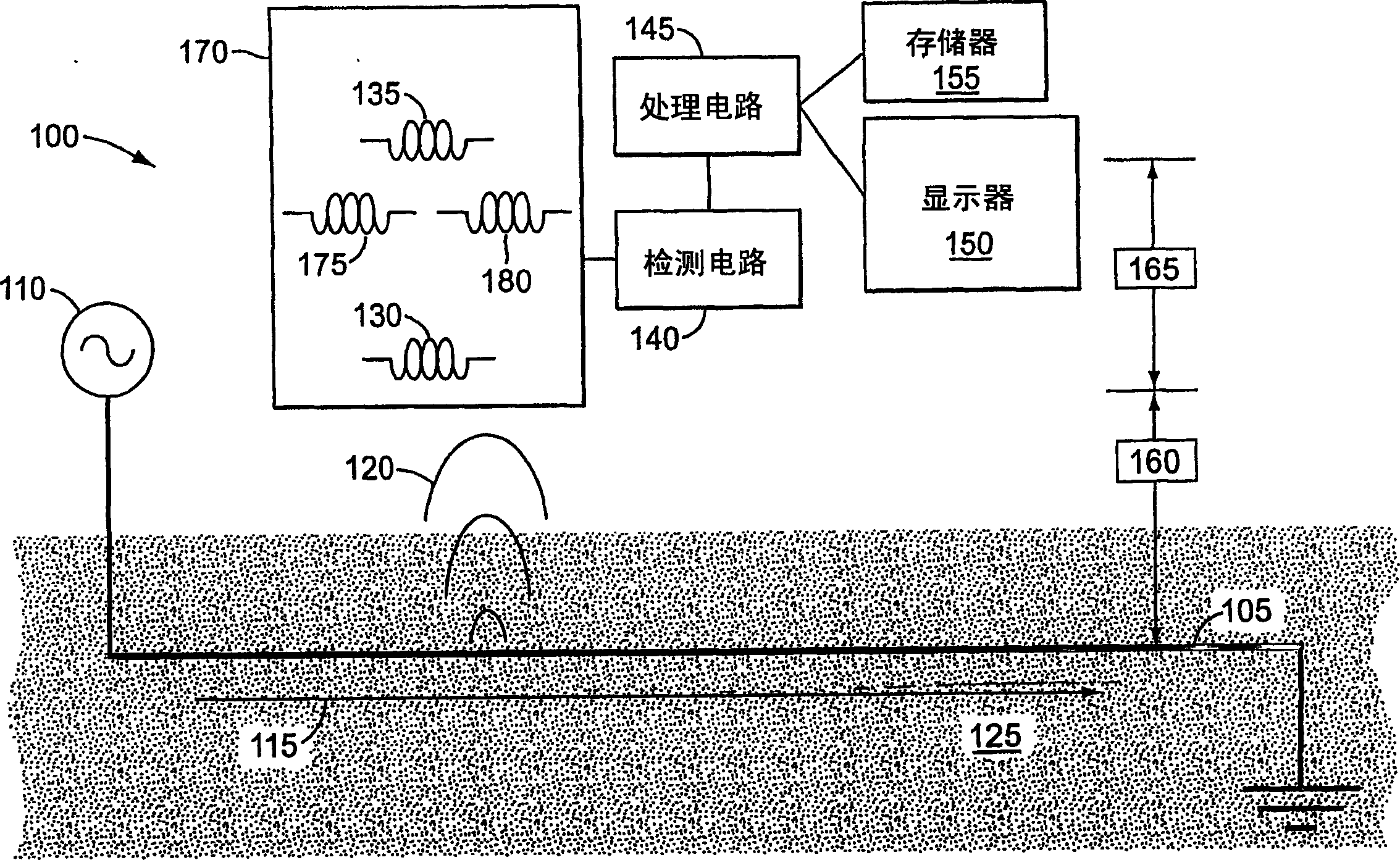
[0027] figure 1 A schematic diagram of a conventional route location system 100 positioned over a route 105 is shown. Transmitter 110 may be coupled to line 105 to sense a current 115 to flow through line 105 . When current 115 flows through line 105 , it generates an electromagnetic field 120 that radiates from line 105 . If the current 115 is constant, the electromagnetic field 120 is a static electromagnetic field. If current 115 varies with time, electromagnetic field 120 is also a time-varying electromagnetic field. A portion of electromagnetic field 120 passes through ground 125 , which can be detected by receiver 170 of locator 100 . exist figure 1 In the illustrated embodiment of locator 100 , receiver 170 includes detectors 130 , 135 , 175 and 180 that can be located to determine the depth of line 105 and the lateral position of line 105 .

[0028] The transmitter 110 is shown in a direct connection mode, ie, the transmitter 110 is electrically connected to the l...


PUM


Abstract

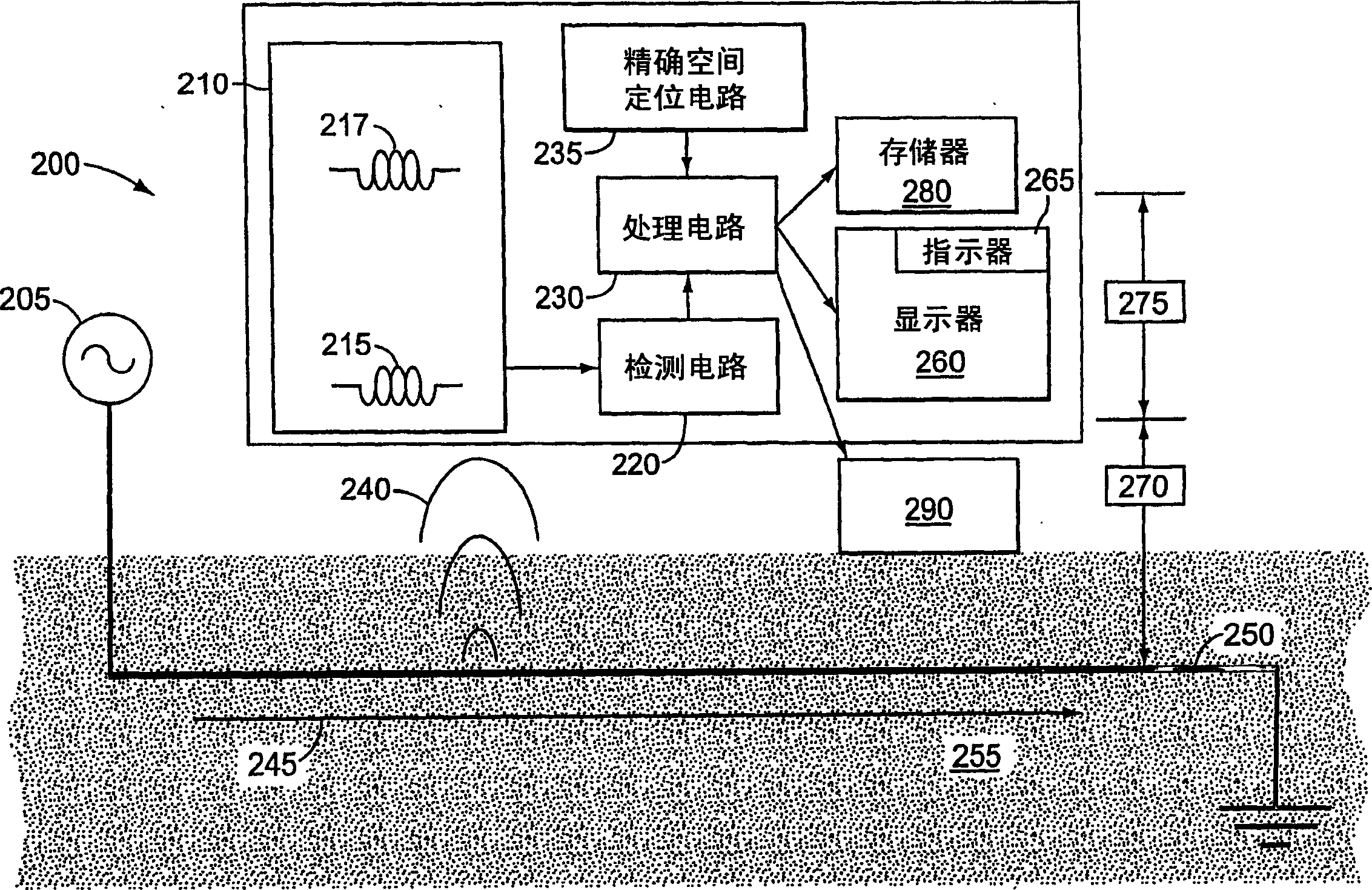
An apparatus is provided for detecting and compensating for field distortion of an underground line by mapping the field strength of a field generated by an electric current buried in the line. Signals from subterranean structures can be mapped against the location of the device. From said graph, a distortion from the expected signal can be determined, indicating the presence of interference or errors of other structures in the position of the detected structure.

Description

technical field [0001] This disclosure relates to the field of electronics and, more specifically, to the application of devices that can be used to locate objects hidden or located underground. Background technique [0002] Line locators are used to locate buried lines such as gas pipes, water pipes, telephone and power cables, etc. A line locator typically includes a transmitter and a receiver. The transmitter causes an electromagnetic field to radiate from the line to be located. The receiver locates the line by detecting the radiated field. The line locator can be operated in one of the following modes: direct connection mode and inductive mode. [0003] In direct connection mode, the transmitter is physically connected to the line to be located, typically at a point on the line above ground. The transmitter generates a voltage at one end of the line, causing current to flow along the conductive line. The current creates a magnetic field around the line that can be ...

Claims


Application Information

Patent Timeline
Patent Type & Authority Applications(China)
IPC IPC(8): G01V3/08
CPCG01V3/08
Inventor 戈登·佩西
Owner VIVAX METROTECH
Learn More