Omnidirectional vision system

A visual device and mounting seat technology, which is applied in the direction of TV, color TV, color TV parts, etc., can solve the problems of robot self-positioning error, difficult correction of barrel distortion, difficult panoramic image, etc., to achieve accurate target recognition, Simple structure, achieve the effect of target recognition

Inactive Publication Date: 2006-06-14
NAT UNIV OF DEFENSE TECH
View PDF0 Cites 5 Cited by
  • Summary
  • Abstract
  • Description
  • Claims
  • Application Information

AI Technical Summary

Problems solved by technology

When the omnidirectional visual system composed of hyperbolic mirrors is located in the center of the site, it can be clearly seen from the obtained panoramic images of the site that the straight lines of the site boundary are imaged as arcs; This barrel distortion is difficult to correct. As far a

Method used


Image

  • Omnidirectional vision system
  • Omnidirectional vision system
  • Omnidirectional vision system

Examples


Embodiment Construction

[0035] The present invention will be described in further detail below in conjunction with the accompanying drawings and specific embodiments.

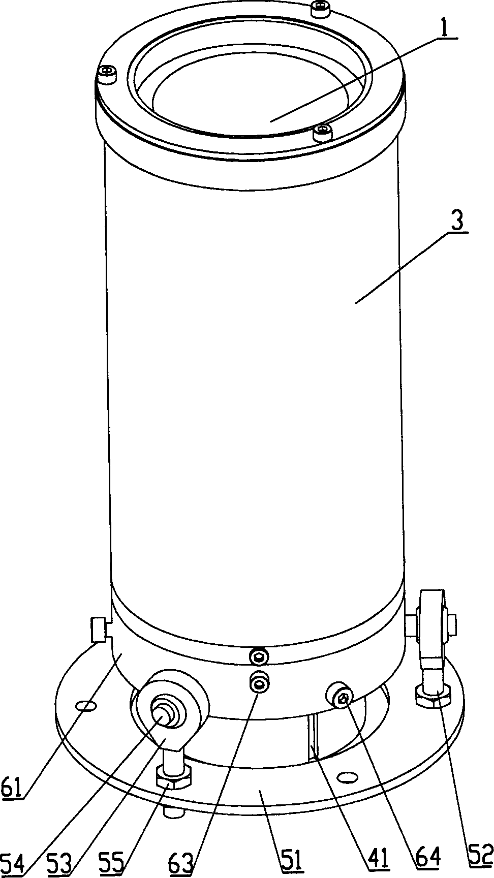
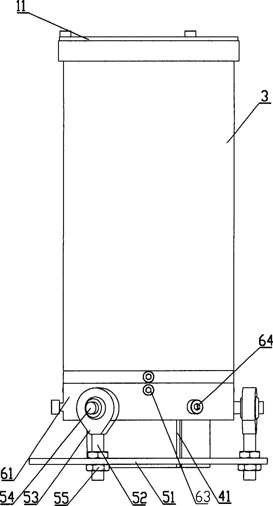
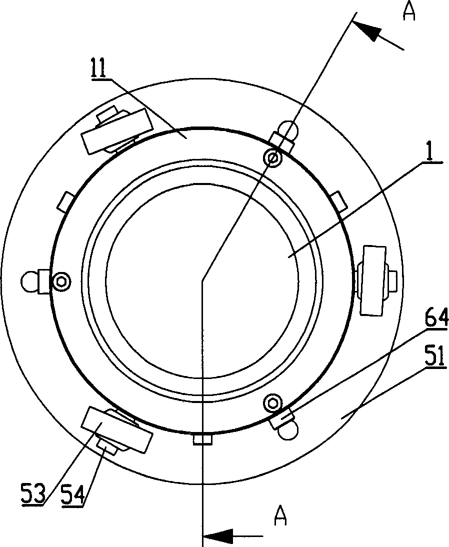
[0036] like figure 1 , figure 2 , image 3 and Figure 4As shown, the omnidirectional visual device of the present invention comprises an omnidirectional mirror 1 and a camera 2, the omnidirectional mirror 1 and the camera 2 are installed in a cylinder 3, the cylinder 3 is made of a transparent material, and the omnidirectional mirror 1 is installed on the top of the barrel 3 through the omnidirectional mirror mount 11, and the camera 2 is installed on the bottom of the barrel 3 through the camera mount 4. The center point of the omnidirectional mirror 1 is located on the optical axis of the camera 2, and the camera is installed Seat 4 is located on the horizontal adjustment mechanism. see Figure 5 , the horizontal adjustment mechanism includes a bottom plate 51, three or four joint bearing connecting rods 52, a joint bearing 5...


PUM


Abstract

The invention discloses an all direction sighting device that includes all direction reflector and camera. All direction reflecting lens and camera are installed in the tunnel body. The center pointer of the al direction reflecting lens is located on the optic axis of the camera, and the camera installation base is set on leveling regulation mechanism. The all direction reflection lens is made up of level geometric proportion lens and vertical geometric proportion lens. The invention could realize the distance relation of panorama and real scene linear.

Description

technical field [0001] The present invention mainly relates to the field of computer vision devices, in particular to an omnidirectional vision device for collecting panoramic images, which can also be applied to mobile robot visual navigation, robot football games, monitoring and monitoring, video conferencing, scene recovery and other technologies field. Background technique [0002] In the prior art, an omnidirectional vision system is composed of an omnidirectional mirror and a camera. The omnidirectional mirror plays the role of reflecting light, and the camera collects the light reflected by the omnidirectional mirror through lens refraction to obtain a panoramic image. For the imaging effect, it also depends on factors such as the positional relationship between the omnidirectional reflector and the camera and whether they are horizontal. In different environments and states, the omnidirectional reflector and the camera must be adjusted in several directions. Precise...

Claims


Application Information

Patent Timeline
IPC IPC(8): G02B27/00G02B5/08G03B37/00H04N5/225
Inventor 卢惠民刘伟刘斐郑志强海丹柳林季秀才
Owner NAT UNIV OF DEFENSE TECH
Why Eureka
Try Eureka